Download
1 / 24
1.32k likes | 3.1k Views
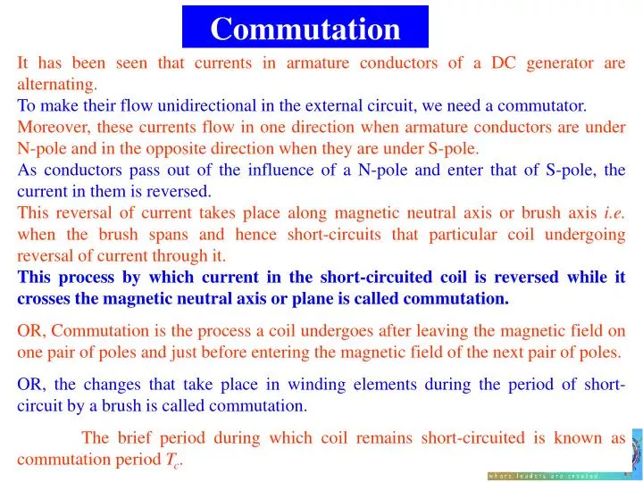
Commutation. It has been seen that currents in armature conductors of a DC generator are alternating. To make their flow unidirectional in the external circuit, we need a commutator.

E N D
Commutation It has been seen that currents in armature conductors of a DC generator are alternating. To make their flow unidirectional in the external circuit, we need a commutator. Moreover, these currents flow in one direction when armature conductors are under N-pole and in the opposite direction when they are under S-pole. As conductors pass out of the influence of a N-pole and enter that of S-pole, the current in them is reversed. This reversal of current takes place along magnetic neutral axis or brush axis i.e. when the brush spans and hence short-circuits that particular coil undergoing reversal of current through it. This process by which current in the short-circuited coil is reversed while it crosses the magnetic neutral axis or plane is called commutation. OR, Commutation is the process a coil undergoes after leaving the magnetic field on one pair of poles and just before entering the magnetic field of the next pair of poles. OR, the changes that take place in winding elements during the period of short-circuit by a brush is called commutation. The brief period during which coil remains short-circuited is known as commutation period Tc.
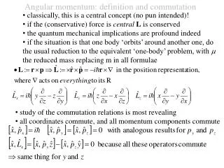
If the current reversal i.e. the change from +I to zero and then to –I is completed by the end of short circuit or commutation period, then the commutation is ideal. If current reversal is not completely by that time, the sparking is produced between the brush and the commutator which results is progressive damage to both. Let us discuss the process of commutation or current reversal in more detail with the help of Fig. 27.10 where ring winding has been used for simplicity. The brush width is equal to the width of one commutator segment and one mica insulation. In Fig. 27.10(a) coil B is about to be short-circuited because brush is about to come in touch with commutator segment ‘a’. It is assumed that each coil carries 20A, so that brush current is 40A. It is so because every coil meeting at the brush supplies half the brush current whether lap winding or wave winding. Prior to the beginning of short circuit, coil B belongs to the group of coils lying to the left of the brush and carries 20A from left to right.
In Fig. 27.10 (b) coil B has entered its period of short-circuit and is approximately at one third of this period. The current through coil B has reduced down from 20A to 10A because the other 10A flows via segment ‘a’. As area of contact of the brush is more with segment ‘b’ than with segment ‘a’, it receives 30A from the former, the total again being 40A. Fig. 27.10(c) shows the coil B in the middle of its short-circuit period. The current through it has decreased to zero. The two currents of value 20A each, pass to the brush directly from coil A and C as shown. The brush contact areas with the two segments ‘b’ and ‘a’ are equal.
In Fig. 27.10(d), coil B has become part of the group of coils lying to the right of the brush. It is seen that brush contact area with segment ‘b’ is decreasing rapidly whereas that with segment ‘a’ is increasing. Coil B now carries 10A in the reverse direction, which combines with 20 A supplied by the coil A to make up 30A that passes from segment ‘a’ to the brush. The other 10A is supplied by coil C and passes from segment ‘b’ to the brush, again giving a total of 40A at the brush. Fig. 27.10(e) depicts the moment when coil B is almost at the end of commutation or short-circuit period. For ideal commutation, current through it should have reversed by now but, as shown, it is carrying 15A only (instead of 20A). The difference of current between coils C and B i.e. 20-15=5A in this case, jumps directly from segment ‘b’ to the brush through air thus producing spark.
If the changes of current through the coil B are plotted on a time base (as shown in Fig. 27.11) it will be represented by a horizontal line AB i.e. a constant current 20A up to the time of being of commutation. From the finish of commutation, the current will be represented by another horizontal line CD. Now, again the current value is FC= 20A, although in the reverse direction. The way in which current changes from its positive value of 20A (BE) to zero and then to its negative value of 20A (=CF) depends on the conditions under which the coil B undergoes commutation. If the current varies at a uniform rate i.e. if BC is a straight line, then it is referred to as linear commutation. However, due to the production of self-induced e.m.f. in the coil the variations follow the dotted curve. It is seen that, in that case, current in coil B has reached only a value of KF=15A in the reversed direction, hence the difference of 5A passes as a spark. So, we conclude that sparking at the brushes, which results in poor commutation is due to the inability of the current in the short-circuited coil to reverse completely by the end of short-circuit period.
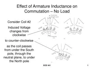
The main causes which retards or delays this quick reversal is the production of self-induced e.m.f. in the coil undergoing commutation. The coil possesses appreciable amount of self-inductance because it lies embedded in the armature which is built up of a material of high magnetically permeability. This self-induced e.m.f. is known as reactance voltage. This voltage, even though of a small magnitude, produces a large current though the coil whose resistance is very low due to a short-circuit. The large circulating current causes sparking at the brushes, undue heating of the brushes and commutator, and unnecessary wear of these components. Naturally, this effect is undesirable, and the circulating current must be eliminated.
There are two practical ways of improving commutation i.e. of making current reversal in the short-circuited coil as sparkles as possible. • These methods are known as: • resistance commutation and • e.m.f. commutation (which is done with the help of either brush lead or interpoles, compoles). Resistance Commutation In this method, low-resistance Cu brushes are replaced by comparative high-resistance carbon brushes. Using Fig. 27.12, it will be seen that how the commutation process is improved by using high resistance carbon brushes instead of Cu brushes.
From Fig. 27.12 [1], it is seen that when the current I from coil C reaches the commutator segment b, it has two parallel paths open to it. The first path is straight from bar b to the brush and the other parallel path is via the short-circuited coil B to bar a and then to the brush. If the Cu brushes (which have low contact resistance) are used, then the current does not follow the second longer path, it would preferably follow the first path. But when carbon brushes having high resistance are used, then current I coming from C will prefer to pass through the second path because (i) the resistance r1 of the first path will increase due to the diminishing area of contact of bar b with the brush, and because (ii) resistance r2 of second path will decrease due to rapidly increasing contact area of bar a with the brush. Hence, carbon brushes have, usually, replaced Cu brushes.
The additional advantage of carbon brushes are that: (i) They are to some degree self-lubricating and polish the commutator, and (ii) Should sparking occur, they would damage the commutator less than when Cu brushes are used. But some of their minor disadvantages are: (a) Due to their high contact resistance a loss of approximately 2 volts is caused. Hence, they are not much suitable for small machines where this voltage forms an appreciable percentage loss. (b) Owing to this large loss, the commutator has to be made somewhat larger than with Cu brushes in order to dissipate heat efficiently without greater rise of temperature, and (c) Because of their lower current density they need larger brush holders.
Interpoles or Compoles These are small poles fixed to the yoke and spaced in between the main poles. They are wound with comparatively few heavy gauge Cu wire turns are connected in series with the armature so that they carry full armature current. Their polarity, in the case of generator, is the same as that of the main pole ahead in the direction of rotation as shown in Fig. 27.13. As their polarity is the same as that of the main pole ahead, the induced an e.m.f. in the coil (under commutation) which helps the reversal of current. The e.m.f. induced by the interpoles (compoles) is known as commutating or reversing e.m.f.. The commutating e.m.f. neutralizes the self-induced e.m.f. thereby making commutation sparkles. As interpoles carry armature current, their commutating e.m.f. is proportional to the armature current.
This ensures automatic neutralization of self-induced e.m.f. which is also due to armature current. Connection for a shunt generator with interpoles are shown in Fig. 27.14. Another function of the interpoles is to neutralize the cross-magnetizing effect of armature reaction. Hence, brushes are not to be shifted from the original position. This neutralization of cross-magnetizing is automatic and for all loads because both are produced by the same armature current. The distinction between the interpoles and compensating windings should be clearly understood. Both are connected in series and their mmfs are such as to neutralize armature reaction. But interpoles additionally supply mmf for counteracting the self-induced e.m.f. in the coil under commutation.
Power Stages of DC Generator Various stages in the case of a DC generator are shown below: A B Mechanical Power Input = Output of Driving Engine or Prime Mover Stray Power losses: Iron, and Friction Losses. Stray Load Loss: 1% of output Electric Power Developed in Armature = EgIa watt Copper Losses • Following are the three generator efficiencies: • Mechanical Efficiency Electric Power Output = VtIL C In the case of Motor 2. Electrical Efficiency 3. Overall or Commercial Efficiency
The overall efficiency can also be calculated by Total Losses in a DC Generator The various losses occurring in a generator can be sub-divided as follows: (a) Copper Losses (b) Magnetic Losses (also known as iron or core losses) (c) Mechanical Losses (d) Stray load loss
(a) Hysteresis loss, (b) eddy current loss, Copper Losses (a) Armature copper loss= Ia2Ra (b) Field copper loss. For shunt generators, it is practically constant and = Ish2Rsh (or VtIsh) For Series generator, = Ise2Rse For Compound generator = Ish2Rsh+ Ise2Rse. (c) The loss due to brush contact resistance. It is usually included in the armature copper loss. Magnetic Losses (also known as iron or core losses) These losses are practically constant for shunt and compound wound generators, because in their case, field current is constant. Mechanical Losses (a) Friction loss at bearing, brush and commutator (b) Air friction or windage loss of rotating armature
Stray Power Losses Stray power losses are those loses that are produced because the armature rotates. Including are the iron or core losses and mechanical losses (friction loss and windage loss). These are also known as rotational losses. Bearing Friction Loss The friction of bearings also consumes energy. Improved bearings reduce the amount of energy consumed and also bearing wear.Improper lubrication increases the friction and causes increased energy consumption. Brush and Commutator Friction Loss Energy is also consumed because of the contact between the brush and the commutator. The coefficient of friction of hard brushes is greater than that of soft brushes. The frictional losses are function of the speed. Speed changes will alter the losses.
Windage Loss Windage loss refers to the energy consumed in moving the air about the armature. The greater the quantity of air moved, the greater the power consumed. The volume of air moved depends upon the speed of the dynamo. As with friction, speed changes will alter the loss. Stray Load Loss The stray load losses are produced as a result of the distortion of the magnetic field by the armature and the interpoles. The distortion causes the flux in the field poles to be unevenly distributed and thereby produces a hysteresis loss. It is generally neglected in motors of 200 hp or less. In larger rated dynamos the stray load loss is assumed to be 1% of the output.
Hysteresis Loss (Wh) This loss is due to the reversal of magnetization of the armature core. Every portion of the rotating core passes under N and S pole alternately. The core undergoes one complete cycle of magnetic reversal after passing under one pair of poles. If P is the number of poles and N the armature speed in rpm then frequency of magnetic reversal is f=PN/120. The loss depends upon the volume and grade of iron, maximum value of flux density Bmax and frequency of magnetic reversals. For normal flux densities (i.e. upto 1.5 Wb/m2), hysteresis loss is given by Steinmetz formula. According to this formula, Where, V=volume of the core in m3; =Steinmetz hysteresis coefficient Value of for: Good dynamo sheet steel=502 J/m3, Silicon steel=191 J/m3, Hard cast steel=7040 J/m3, Cast steel=750-3000 J/m3, and cast iron=2700-4000 J/m3.
Eddy Current Loss (We) When the armature core rotates, it also cuts the magnetic flux. Hence, an emf induced in the body of the core according to the laws of electromagnetic induction. This emf though small, sets up large current in the body of the core due to its small resistance. This current is known as eddy current. The power loss due to the flow of this current is known as eddy current loss. Eddy current loss We is given by the following relation: where Bmax= maximum flux density f=frequency of magnetic flux reversals t=thickness of each lamination V=volume of armature core.
In order to reduce this loss and the consequent heating of the core to a small value, the core is built up of thin laminations. These core laminations are insulated from each other by a thin coating or varnish. The effect of laminations is shown in Fig. 24.59. Due to the core body being one solid iron piece (Fig. 24.59a), the magnitude of eddy currents is large. As armature cross-sectional area is large, its resistance is very small, hence eddy current loss is large. In Fig. 24.59b, the same core has been split up into thin circular discs insulated from each other. It is seen that now each current path, being of much less cross-section, has a very high resistance. Hence, magnitude of eddy currents is reduced considerably thereby drastically reducing eddy current loss.
Total loss=armature copper loss +Wc= Eddy current loss is reduced by using laminated core but hysteresis loss cannot be reduced this way. For reducing the hysteresis loss, those metals are chosen for the armature core, which have a low hysteresis coefficient. Constant or standing Losses Field Cu loss is constant for shunt and compound generators. Hence, stray losses and shunt Cu loss are constant in their case. These losses are together known as standing or constant losses Wc. Hence for shunt and compound generators, Armature Cu loss Ia2Ra is variable loss because it varies with the load current. Total loss= variable loss + constant loss Wc.
However, if Ish is negligible as compared to load current, then Ia=IL (approximately), then generator input= Generator input =Output + Losses Condition for Maximum Efficiency Generator output = VtIL Now, efficiency is maximum when denominator is minimum i.e. when Hence, generator efficiency is maximum when, Variable loss = Constant Loss The load current corresponding to maximum efficiency is given by the relation
Example 26. 23 A 10 kW, 250 V, DC, 6 pole shunt-generator runs at 1000 rpm when delivering full-load. The armature has 534 lap-connected conductors. Full-load Cu loss is 0.64 kW. The total brush drop is 1 V. Determine the flux per pole. Neglect shunt-current. Solution: Since shunt-current is negligible; there is no shunt Cu loss. The Cu loss occurs in armature only. IL=Ia=10,000/250=40 A; Armature drop= IaRa=400.4=16 V; Brush drop=1 V.
(ii) Armature Cu loss= Example 26. 24(a) A shunt-generator delivers 195 A at terminal p.d (potential difference) of 250 V. The armature resistance and shunt field resistance are 0.02 and 50 respectively. The iron and friction losses equal 950 W. Find: (i) EMF generated, (ii) Cu losses, (iii) output of the prime mover, and (iv) commercial, mechanical and electrical efficiencies. Solution: (i) Ish=250/50=5 A; Ia=195+5=200 A Armature voltage drop =IaRa= 2000.02=4 V; generated emf= 250+4=254 V Shunt Cu loss= VIsh= 2505=1250 W;Total Cu loss = 1250 + 800 =2050 W (iii) Stray losses = 950 W;Total losses= 2050+950= 3000 W Output= 250195 = 48,750 W;Input= 48,750+3,000= 51,750 W Output of prime mover = 51,750 W (iv) Generated input= 51,750 W;Stray losses=950 W Electrical power produced in armature =51,750 –950=50,800 W Mechanical efficiency, m=(50,800/51,750)100=98.2% Electrical or Cu losses= 2050 W Electrical efficiency, e =(50,800100)/(48,750+2050)=95.9% Commercial or overall efficiency, c =(48,750100)/(51,750)=94.2%
Example 26. 25 A shunt-generator has a full-load current of 196 A at 220 V. The stray losses are 720 W and the shunt field coil resistance is 55 . If it has a full-load efficiency 88%, find the armature resistance. Also, find the load current corresponding to maximum efficiency. Solution: Output = 220 196 = 43,120 W; =88% (overall efficiency) Electrical input = 43,120/0.88 = 49,000 W;Total losses= 4900-43,120 = 5,880 W Shunt field current – 220/55=4 A;So, Ia= 196+4 = 200 A; Shunt Cu loss = 2204 = 880 W;Stray losses = 720 W; Constant losses = 880 + 720 = 1,600 W Armature Cu loss = 5,880 – 1,600= 4,280 W For maximum efficiency,