Download
1 / 9
550 likes | 1.89k Views
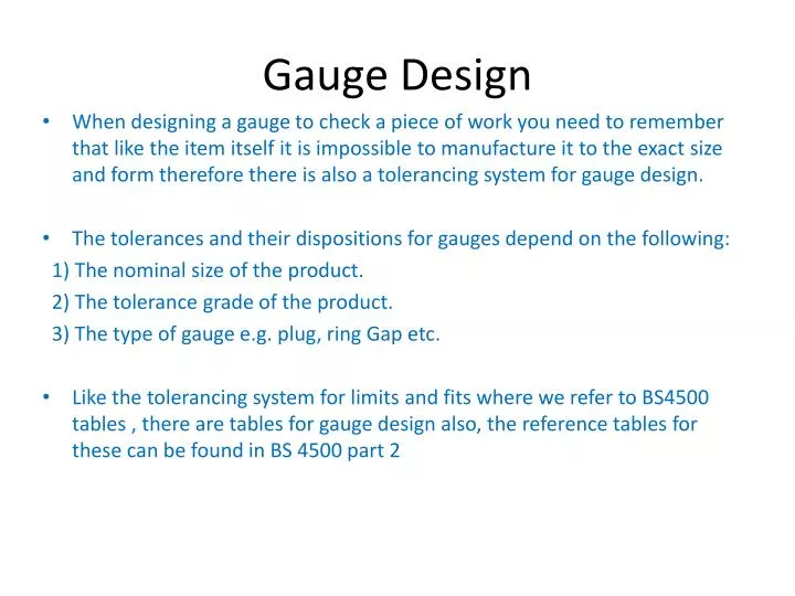
Gauge Design. When designing a gauge to check a piece of work you need to remember that like the item itself it is impossible to manufacture it to the exact size and form therefore there is also a tolerancing system for gauge design.

E N D
Gauge Design • When designing a gauge to check a piece of work you need to remember that like the item itself it is impossible to manufacture it to the exact size and form therefore there is also a tolerancing system for gauge design. • The tolerances and their dispositions for gauges depend on the following: 1) The nominal size of the product. 2) The tolerance grade of the product. 3) The type of gauge e.g. plug, ring Gap etc. • Like the tolerancing system for limits and fits where we refer to BS4500 tables , there are tables for gauge design also, the reference tables for these can be found in BS 4500 part 2
Plug Gauge Application No-Go Gauge U/L = Hole U/L + H/2 No-Go Gauge L/L = Hole U/L - H/2 Go Gauge U/Limit = Hole L/L + z + H/2 Go Gauge L/Limit = Hole L/L + z - H/2 Wear Limit = Hole L/L - Y Application of Gauge tolerancing
Worked Example of Application • Calculate the dimensions for the Go and No-Go elements for a plug gauge for checking a hole of nominal diameter 25mm and tolerance grade H7 (IT7). Solution • Refer to BS4500 Tables of Limits and Fits ( Hole Basis) and look down left hand column to find correct size (25mm) look along row to corresponding fit on top row (H7) and make note of sizes (+0 and +0.021) • Using information collected Hole Lower Limit = 25.00 + 0.00 = 25.00mm Hole Upper Limit = 25.00 + 0.021 = 25.021mm • Refer to table 4.5 location of tolerances and limit of maximum gauge wearand look down left hand column and locate row containing correct size (25mm) and look along row to corresponding column for Z = (distance between centre of tolerance zone for gauge and lower limit of work piece) (3 ) = ( 0.003mm) • Using the same row obtain value for Y = wear limit (3 ) = ( 0.003mm) • Refer to Table 4.4 Tolerance grades for gauges , look along the column at the top and locate the grade IT7 for work piece, look down the column to the corresponding row for plug gauges in first column this will show IT grade 3 for size and IT grade 2 for form. • Refer back to Table 4.5 and look down left hand column to find correct size 25mm and look along row to corresponding column IT grade 2 to find value of (H) tolerance for plug gauge = (0.004mm) • Using Data Obtained • Upper Limit of Go Gauge = Hole Lower Limit 25.00 + (Z) 0.003 + (H/2) 0.002 = 25.005mm • Lower Limit of Go Gauge = Hole Lower Limit 25.00 + (Z) 0.003 – (H/2) 0.002 = 25.001mm • Wear Limit = Hole Lower Limit 25.00 – (Y) 0.003 = 24.997mm • Upper Limit of NO-GO Gauge = Hole Upper Limit 25.021 + (H/2 ) 0.002 = 25.023mm • Lower Limit of NO-GO Gauge = Hole Upper Limit 25.021 – (H/2) 0.002 = 25.019mm
Use of Table of Deviations for Plug, Ring and Gap Gauges to calculate limits of size • Calculate the dimensions for the Go and No-Go elements for a plug gauge for checking a hole of nominal diameter 25mm and tolerance grade H7 (IT7). • For most practical purposes it is not necessary to use the previous method (first principles ) to calculate gauge limits of size, we can obtain the sizes direct from tables of deviation for plug ring and gap gauges up to 180mm in size • Refer to Table 4.6 and locate size 25mm in first column under plug gauges, • Look along row to column for IT7 (product tolerance) and obtain the deviations for Go and No-Go gauges • Upper limit of Go Gauge = Hole Lower Limit 25.00 + 0.005 = 25.005mm • Lower Limit of Go Gauge = Hole Lower Limit 25.00 + 0.001 = 25.001mm • Wear Limit = Hole lower Limit 25.00 – 0.003 = 24.997mm • Upper limit of No-Go Gauge = Hole Upper Limit 25.021 + 0.002 = 25.023mm • Lower Limit of No-Go Gauge = Hole Upper Limit 25.021 – 0.002 = 25.019mm