Download
1 / 12
120 likes | 281 Views
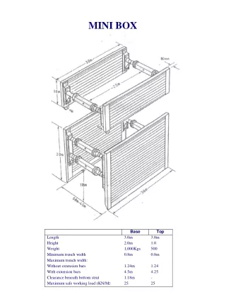
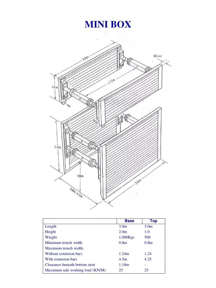
MINI BOX. STANDARD BOX. MAGNUM BOX. SPINDLE ASSEMBLY. FITTING EXTENSION BARS.

E N D
FITTING EXTENSION BARS If 3 or more extension bars wide it is more convenient to fit 2 bars to the side of the box which is left laying on the ground and the other bars to the side which has been removed, then joining the two side together can be done at a more convenient height
REMOVAL OF EXTENSION BARS Lay the box on its side and reverse the previous operations METHOD OFTURNING BOXES
SETTING BOXES TO CORRECT WIDTH Base Unit Set the width of the top struts to the trench width you require by inserting the winding bar either between the flanges of the spindles, if no extension bars are used or through the hole in the extension bars and screwing the spindles in or out as required. Note it is easier to adjust the spindles if each spindle is wound out a little at a time. Continue adjusting all the spindles until the top of the box is set to the correct trench width measuring from the outside of the panels. Set the cutting edge of the box to 35 - 40mm wider than the top of the box by adjusting the bottom spindle. Top Unit Set these to the same width as the top of the base unit. PLEASE NOTE: Do not lift box thus!!
INSTALLATION • Check all nuts & bolts on units are right • Check that the box is set to the correct width and that the cutting edge is 35 -40mm wider than the top of the box • Dig a trench approximately 600mm to 1000mm deep to the correct trench width on the line of the excavation and using the 4: leg chain sling place the box in the trench • By digging within the units and pushing down on the vertical soldiers, the boxes can be sunk to the required depth. In heavy soil conditions this may be made easier if the bucket of the excavator is filled with excavated material • ALWAYS PUSH ON THE SOLDIERS NEVER ON THE TOP OF THE PANELS • NOTE: The shock absorber system on boxes allows the panels of the boxes to moved independently of each other. The maximum movement of the panels form the horizontal is 100% of the width of the box, this must never be exceeded. • When pushing on the soldiers always push down on each side in sequence, never push soldiers positioned diagonally, I.e 1 & 2 or 3 & 4, never 1 & 3 or 2 & 4. • As the excavation progress top units should be added to the base units. Top units should be used with the shock absorber to the top of the spindles. • Always ensure that the correct connectors are fitted and the pins are inserted. • When the excavation is complete and the box sunk to full depth always ensure that the struts are left in the horizontal position. WE also suggest that a small gap be left between boxes to allow them to be moved about to facilities extraction from the trench. • If using the boxes for the construction of a manhole or pit, it is essential that the struts are not used as shoring, for the trench sheets supporting the ends if the excavation. We suggest that large timbers be cut to the width of the excavation and that these should be supported from the ends of the panels and not the cross struts.
EXTRACTION When pipe laying has been completed the units can be extracted gradually as backfilling progresses. The simple leg chain should be used to free the box from the excavation. Once the box is free, two legs of the 4-leg chain can be attached to one of the panels to pull this side up and the operation repeated on the other side When the box becomes very free attach one leg of the 4-leg chain to each corner to lift the box from the excavation. NOTE: The shock absorber system on the boxes allows the panels of the boxes to be moved independently of each other. The maximum movement of the panels from the horizontal is 10% of the width of the box. This must never be exceeded. When boxes are installed they must always be positioned with the strut in the horizontal position.