Download
1 / 40
400 likes | 623 Views
Entity Relationship Diagrams and Relational DBs. BSAD 141 Dave Novak. Topics Covered. ERD (entity relationship diagram) Data Modeling Entity – vs - Entity set Attribute – vs - Relationship Types of attributes and their domain Characteristics of relationships Degree Connectivity

E N D
Entity Relationship Diagrams and Relational DBs BSAD 141 Dave Novak
Topics Covered • ERD (entity relationship diagram) • Data Modeling • Entity –vs- Entity set • Attribute –vs- Relationship • Types of attributes and their domain • Characteristics of relationships • Degree • Connectivity • Existence
Modeling • Why would it be necessary or useful to model the structure of a database system?
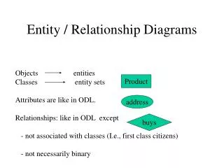
Modeling • Data Model • Entity-Relationship Diagram (ERD) • Popular model that focuses on data
ERD • ERD: Graphical “blueprint” for the exact design and structure of a relational DB • Shows details of things organization collects data about and how those things are related
Relational Database Management System RDBMS • A very popular, widely used DBMS • Made possible by modern computing power –computer must a lot of processing work • User does not need to understand the underlying structure of the database
Relational Databases • Based on organization of data in two-dimensional tables connected via relationships • Tables are “linked” using a common data element (attribute) that appears in both tables • By linking tables via relationships users can navigate the database and extract and combine data from different tables
Relational Databases • The Table is the fundamental component in a relational database • All data are divided into different tables • This approach provides a much easier way to manage data • Data are essentially “grouped” by common themes and then connected by relationships in a logical manner based on the ERD
Relational Databases • A relationship is a connection between two or more simple two-dimensional tables that consist of rows (entity / records) and columns (attributes / fields) of data • Each entity is a unique observation and the attributes are the common characteristics that are used to describe all the entities
Relational Databases • Power of an RDBs comes from ability to quickly find and bring together data stored in separate tables using queries, forms, and reports • RDBs utilize the Structured Query Language (SQL) • A programming language used to manage data in a RDB
Relational Databases CLASS SECTION Table
Review What is the entity set represented here? What is an example of an entitywithin the entity set? What are some of the attributes of the entity? Why is the first field – Employee ID – underlined?
Primary Keys • Each record/entity must have a attribute (field/column) or set of attributes that uniquely identifies that specific entity from all the other entities stored in the table • The unique attribute (or set of attributes) is called the primary key
Primary Keys • For our purposes: • ALL relational DB tables must have a primary key • ALL entities within the table must have a unique primary key value • The primary canbe created by you • Doesn’t have to provide value-added information • Can be a combination of fields/attributes • Can be sequential numbers • Can be a combination of letters and numbers • Cannot be repeated or left blank for an entity
Review Key Terminology • Entity Set / Table (has a name that directly relates to the primary information stored in the table) • Entity / Record (this is a row in a table) • Attribute / Field (this is a column in the table that describes a characteristic of the entity) • Relationship (an association or linkage between two (+) tables)
Different Types of Attributes • Simple –vs- composite • Single valued –vs- multi-valued
Attribute Domain • The collection or range of all possible allowable values an attribute may take on • EmpDOB: list of all valid employee birth • NumDependents: positive integers from 0 to 15 • Height: positive real numbers between 36.0 and 84.0 inches. • UnionMember: logical yes (true) or no (false) • EmpSSN: list of valid social security numbers
Value for Each Attribute • Each data attributetakes on aspecific “value”: • One particular instance of an entity’s attribute • e.g. Employee attributes:
Relationships • Entities are connected to one another via relationships • The association between two or more entities • We will discuss three (3) important characteristics of relationships: • 1) Degree • 2) Connectivity • 3) Existence
Relationship Degree • Loosely equal to the number of entities involved in a particular relationship • Could also view this more simplistically as the number of tables “linked” by each relationship • 1= Unary (aka recursive) • 2= Binary • 3= Ternary
Relationship Connectivity • Three types of connectivity relationships are used to describe associations between the entities in different tables • How are entities logically connected in the DB? • 1) One-to-Many • 2) Many-to-Many • 3) One-to-One
Relationship Connectivity 1:1 Employee Vehicle Company Vehicle #1 Company Vehicle #2 Company Vehicle #3 Employee #1 Employee #2 Employee #3 1 1 This relationship connectivity shows that each employee can be associated with only one company vehicle and that each company vehicle can be associated with only one employee. In this case, the RDB will be structured in a manner that matches a specific employee to a specific company car each and every day. Each car would be explicitly linked to a particular employee
Relationship Connectivity 1:M Department Employee Accounting Department Human Resources Dept Employee #1 Employee #2 Employee #3 Employee #4 M 1 This relationship connectivity shows that each employee can be associated with only one organizational department (employees cannot simultaneously be assigned to, or work in, two different departments). However, each department can be staffed with many / multiple employees
Relationship Connectivity M:M Product Customer Product #1 Product #2 Product #3 Product #4 Customer #1 Customer #2 Customer #3 M M This relationship connectivity shows that customer can be associated with many different products and that each product can be associated with many different customers This relationship will be modeled in a special way!!
Relationship Connectivity • One-to-Many relationship • A professor can teach many different class sections • Each class section is taught by only one professor • A customer account can contain many invoices • Each invoice is associated with only one customer account
Relationship Connectivity • One-to-Many example • Relationship is labeled 1:M Each teaches M Class Section Professor Each is taught by 1 Read: left to right on the top of the line Read: right to left on the bottom of the line
Relationship Connectivity • Many-to-Many relationship • Employee has many job skills • Each job skill can be learned by many employees • Student can take many class section • Each class section can be taken by many students
Relationship Connectivity • One-to-One relationship • Employee is assigned to one Company Car • Each Company Car is assigned to only one employee
Relationship Connectivity • Why does this matter? • Logically the relationship needs to make sense • Don’t want the database functionality to allow relationships that are not feasible or practical • From a practical perspective, the foreign key always goes on the many side of the relationship – need to get this correct • Special implementation of M:M & 1:1
Relationship Existence • Denotes whether participation in a relationship is required (or not), and the minimum and maximum number of entities that participate in a particular relationship • Mandatory: The existence of one entity depends on the existence of another entity • Optional: The existence of one entity is independent of the existence of another entity
Mandatory Relationship Existence Example 1:M Employee Department Accounting Department Human Resources Dept Employee #1 Employee #2 Employee #3 Employee #4 The existence of an instance of employee (an individual employee) depends on the existence of a department where the employee will be assigned In this case, the entity set Department will need to be populated before the entity set Employee is populated
Optional Relationship Existence Example 1:M Employee Department Accounting Department Human Resources Dept Employee #1 Employee #2 Employee #3 Employee #4 The existence of an instance of employee (an individual employee) is independent of the existence of a department where the employee will be assigned In this case, the entity instance employee #4 can be created without the need to assign that employee to a department
Relationship Existence Example 1:M Course Course Section BSAD 141 BSAD 173 BSAD 120 CRN 5099 CRN 5060 CRN 5061 CRN 5062 Discuss…
Investigating Relationships 1:M relationship This relationship states that each supplier can provide (or distributes) many different products (1, 2, … n), but each individual product is provided by (or distributed by) only one supplier In this case, the structure would not allow a specific product to be provided by (or distributed by) to more than one supplier Can provide M Product Supplier 1 Is provided by
Supplier Table Can provide M Product Supplier 1 Is provided by
Product Table Can provide M Product Supplier 1 Is provided by
Product Table Notice that SupplierID is not an attribute of Product – it is the PK of the Supplier table and will be the FK (to the Supplier table) in the Product table
Investigating Relationships • The 1:M relationship example • The Supplier ID attribute in the Product table is a foreign key that links the individual products in the Product table to a specific supplier in the Supplier table
Learning Outcomes • Describe the differences between ERDs and DFDs • Describe importance of relational DBs • Familiar with all terminology: tables, relationships, entities, attributes, keys, etc • Understand how to implement a relationship • Discuss / define the 3 characteristics of relationships