Download
1 / 30
300 likes | 432 Views
EE 462L dc and ac Power Distribution Systems Fall 2008. History. Competing technologies for electrification in 1880s: Edison: dc. Relatively small power plants (e.g. Pearl Street Station). No voltage transformation. Short distribution loops – No transmission

E N D
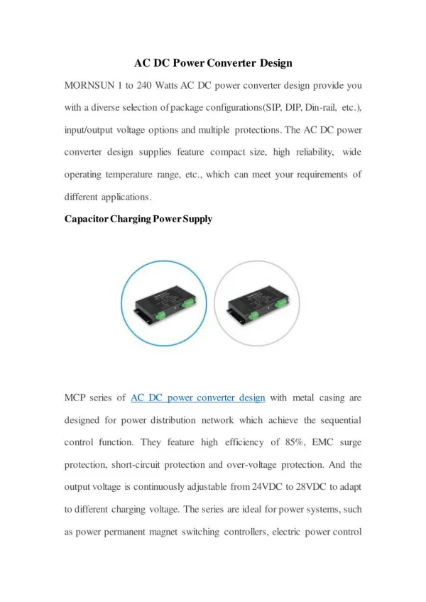
EE 462L dc and ac Power Distribution Systems Fall 2008
History • Competing technologies for electrification in 1880s: • Edison: • dc. • Relatively small power plants (e.g. Pearl Street Station). • No voltage transformation. • Short distribution loops – No transmission • Loads were incandescent lamps and possibly dc motors (traction). Pearl Street Station: 6 “Jumbo” 100 kW, 110 V generators “Eyewitness to dc history” Lobenstein, R.W. Sulzberger, C.
History • Competing technologies for electrification in 1880s: • Tesla: • ac • Large power plants (e.g. Niagara Falls) • Voltage transformation. • Transmission of electricity over long distances • Loads were incandescent lamps and induction motors. Niagara Falls historic power plant: 38 x 65,000 kVA, 23 kV, 3-phase generatods http://spiff.rit.edu/classes/phys213/lectures/niagara/niagara.html
History • Edison’s distribution system characteristics: 1880 – 2000 perspective • Power can only be supplied to nearby loads (< 1mile). • Many small power stations needed (distributed concept). • Suitable for incandescent lamps and traction motors only. • Higher cost than centralized ac system. • Used inefficient and complicated coal – steam actuated generators (as oppose to hydroelectric power used by ac centralized systems). • Not suitable for induction motor. • Cannot be transformed into other voltages (lack of flexibility). Vdc,1 dc MOTOR dc GENERATOR Vdc,2
History • Traditional technology: the electric grid: • Parts: generation, transmission, and distribution. • Centralized and passive architecture. • Extensive and very complex system. • Complicated control. • Not reliable enough for some applications. • Relatively inefficient. • Stability issues. • Vulnerable. • Lack of flexibility.
History • Edison’s distribution system characteristics: 2000 – future perspective • Power supplied to nearby loads is more efficient, reliable and secure than long power paths involving transmission lines and substations. • Many small power stations needed (distributed concept). • Existing grid not suitable for dc loads (e.g., computers) or to operate induction motors at different speeds. Edison’s system suitable for these loads. • Power electronics allows for voltages to be transformed (flexibility). • Cost competitive with centralized ac system. • Can use renewable and alternative power sources. • Can integrate energy storage. • Can combine heat and power generation.
Conventional (ac) datacenters • Typical configuration: • Total power consumption: > 5 MW (distribution at 208V ac)
Conventional (ac) datacenters • Data centers represent a noticeable fast increasing load. • Increasing power-related costs, likely to equal and exceed • information and communications technology equipment cost in the • near to mid-term future. • Servers are a dc load • 860 W of equivalent coal power is needed to power a 100 W load
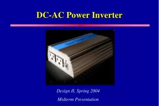
New (dc) datacenters • Use of 380 Vdc power distribution for: • Fewer conversion stages (higher efficiency) • Integration of local sources (and energy storage). • Reduced cable size
Data centers efficiency comparison dc vs. ac • A 380Vdc power distribution standard is currently under study by the IEC Brian Fortenbery and Dennis P. Symanski, GBPF, 2010
New distributed (dc) datacenters • Many “small” distributed data centers powered locally and with a coordinated operation • Energy is used more effectively. • Generation inefficiencies is energy that is not harvested (i.e. converted), contrary to inefficiencies in conventional power plants which represent power losses.
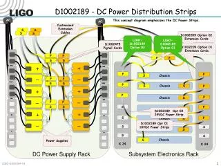
Utility dc distribution Jonbok Bae, GBPF 2011
Traditional Electricity Delivery Methods:Reliability Traditional grid availability: Approximately 99.9 % Availability required in critical applications: Approximately 99.999%
Traditional Electricity Delivery Methods:Reliability • Large storms or significant events reveal the grid’s reliability weaknesses: • Centralized architecture and control. • Passive transmission and distribution. • Very extensive network (long paths and many components). • Lack of diversity. http://www.nnvl.noaa.gov/cgi-bin/index.cgi?page=items&ser=109668 http://www.gismonitor.com/news/newsletter/archive/092205.php http://www.oe.netl.doe.gov/docs/katrina/la_outage_9_3_0900.jpg
Microgrids • dc vs. ac in microgrids • Microgrids are considered to be locally confined and independently controlled electric power grids in which a distribution architecture integrates loads and distributed energy resources—i.e. local distributed generators and energy storage devices—which allows the microgrid to operate connected or isolated to a main grid
dc Homes • dc in homes allows for a better integration of distributed generation, energy storage and dc loads. • With a variable speed drive air conditioners can be operated continuously and, hence, more efficiently (about 50%) WIND GENERATOR PV MODULES LED LIGHTS (DC) MAIN DC BUS REFRIGERATOR (LOAD) ENERGY STORAGE ELECTRIC VEHICLE AIR CONDITIONER EPA 430-F-97-028 FUEL CELL
Comparison of ac vs. dc systems • Advantages of dc: • Higher availability • At least 5 % more efficient than ac • Enables for more dense systems • Easier control • Easier to connect in parallel • More flexible architectures • Most critical loads and future loads are, actually, dc • Most local sources are dc (for diverse input) • Allows for a simpler and usually direct way to integrate energy storage • Power quality control • Advantages of ac: • Usually tends to be more cost efficient than dc (economics of scale) • Simpler circuit protections • Adds one more control degree of freedom
dc power architectures in electric ships • Circuit protection: conventional approach
dc power architectures in electric ships • Circuit protection: power electronics or solid state switches approaches.
Dc systems faults management • In power electronic distributed architectures, faults may not be properly detected because, without a significant amount of stored energy directly connected to the system buses, short-circuit currents are limited to the converter maximum rated current plus the transitory current delivered by the output capacitor. • If the latter is not high enough, the protection device will not trip and the fault will not be cleared. • In this case, the converter will continue operation delivering the maximum rated current but with an output voltage significantly lower than the nominal value. • Consider the following situation
Dc systems faults management • With C = 600 μF, the fault is not properly cleared and voltage collapse occurs for both loads.
Dc systems faults management • To avoid the situation described above, the converter output capacitance has to be dimensioned to deliver enough energy to trip the protection element. • One approach is to calculate the capacitance based on the maximum allowed converter output voltage drop. However, this is a very conservative approach that often leads to high capacitance values. • Another option is to calculate the capacitance so that it can store at least enough energy to trip the protection device, such as a fuse. • Fuse-tripping process can be divided into two phases: • pre-arcing • Lasts for 90% of the entire process. • During this phase, current flows through the fuse, which heats up. • arcing • the fuse-conducting element melts and an arc is generated between the terminals. The arc resistance increases very rapidly, causing the current to drop and the voltage to increase. Eventually the arc is extinguished. At this point, the current is zero and the voltage equals the system voltage.
Dc systems faults management • The energy during pre-arcing is • where TF is the total fault current clearing time, RF is the fuse resistance before melting, and IC,F is the limiting case capacitor current during the fault. • IC,F equals the fault current less the sum of the converter current limit and other circuit currents. For larger capacitances than the limit case, the converter current may not reach the rated limit value, so IC,F might be slightly higher than in the limit case. • .If a linear commutation is assumed, the portion of the arcing phase energy supplied by the capacitor is • Thus,
Dc systems faults management • With VS = VF = 50 V, IC,F = 135 A, RF = 1 mΩ, and considering a typical value for TF of 0.1 s, the minimum value of C is 900 μF. If the previous system is simulated with C = 1mF, then • Ringing on R2 occurring when the fault is • cleared can be eliminated by adding a • decoupling capacitance next to R2
Dc systems faults management • Additional simulation plots
Series faults in ac systems • Series faults occur when a cable is severed or a circuit breaker is opened, or a fuse is blown…. Then an arc is observed between the two contacts where the circuit is being opened. • The arc is interrupted when the current is close to zero. • Due to cable inductances, voltage spikes are observed when the arc reignites.
Series faults in ac systems • Visually, arcs in ac series faults are not very intense
Series faults in dc systems • In dc arcs last longer (because there are no zero crossings for the current) but no voltage spikes are generated.
Series faults in dc systems • Dc arcs last longer than ac ones, are much more intense and may damage the contacts.