Download
1 / 27
320 likes | 781 Views
Extrusion and Drawing of Metals. Chapter 15. Direct-Extrusion. Extrusion process: metal is forced through a shaped die to form a product with reduced but constant x-sec.(F15.1) Cold extrusion: combination of Extrusion and forging operations.

E N D
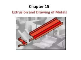
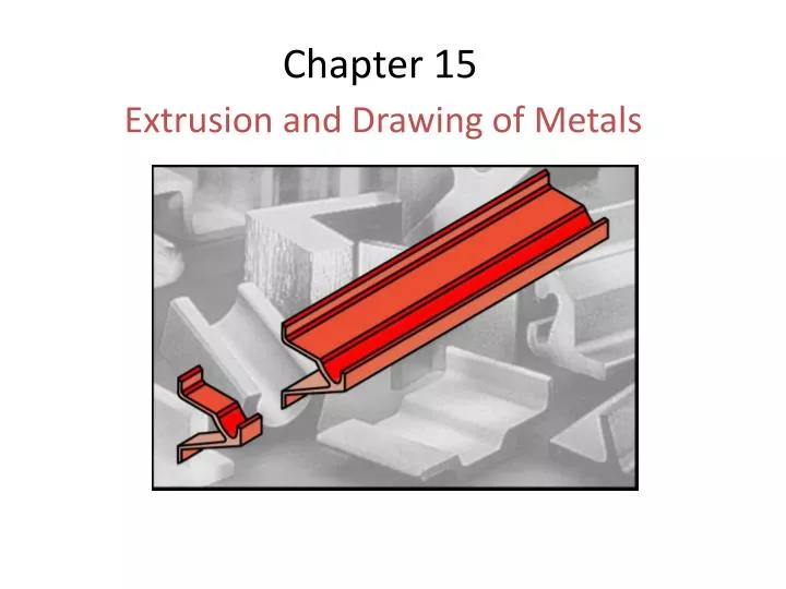
Extrusion and Drawing of Metals Chapter 15
Direct-Extrusion • Extrusion process: metal is forced through a shaped die to form a product with reduced but constant x-sec.(F15.1) • Cold extrusion: combination of Extrusion and forging operations. Figure 15.1 Schematic illustration of the direct-extrusion process.
Extrusions and Products Made from Extrusions Figure 15.2 Extrusions and examples of products made by sectioning off extrusions. Source: Courtesy of Kaiser Aluminum.
The Extrusion Process Direct extrusion (forward extrusion): round billet is placed in a chamber and forced through a die opening by a hydraulically-driven ram or pressing stem (F15.1). Indirect extrusion (reverse, inverted, or backward extrusion): the die moves toward the billet (F15.3a). • It has the advantage of having no billet-container friction, since there is no relative motion. Thus, indirect extrusion is used on materials with very high friction, such as high strength steels. Hydrostatic Extrusion: the billet is smaller in diameter than the chamber (which is filled with a fluid), and the pressure is transmitted to the fluid by a ram. The fluid pressure results in triaxial compressive stresses acting on the workpiece and thus improved formability (F15.3b). Lateral extrusion (Fig. 15.3c) is used for the sheathing of wire and the coating of electric Wire with plastic.
Types of Extrusion Figure 15.3 Types of extrusion: (a) indirect; (b) hydrostatic; (c) lateral;
Process Variables in Direct Extrusion • Geometric Variables • Die angle, a • Extrusion ratio, R: Ratio of x-sec areas, Ao/Af. • Temperature of billet. • Ram speed. • Type of used lubricant. Figure 15.4 Process variables in direct extrusion. The die angle, reduction in cross-section, extrusion speed, billet temperature, and lubrication all affect the extrusion pressure.
Extrusion Force • Extrusion Force, • K: the extrusion constant, (F15.6). • Ex: P15.1, Figure 15.5 Extrusion constant k for various metals at different temperatures. Source: After P. Loewenstein
15.3 Process Parameters-Extrusion Practice • Because they have high ductility, wrought aluminum, copper, and magnesium and their alloys, as well as steels and stainless steels, are extruded with relative ease into numerous shapes. • Other metals (such as titanium and refractory metals) also can be extruded, but only with some difficulty and considerable die wear. • Extrusion ratio, R: 10-100. • R: at least 4 to work the material plastically through the bulk of the work-piece. • Extruded products usually less than 7.5m long, because of difficulty in handling greater lengths, but they can be as long as 30m. • Ram speeds: up to 0.5m/s • Lower speeds are preferred for more ductile materials: AL, Mg, Cu. • Higher speeds for less ductile materials: steels, titanium, and refractory alloys. • Dim tolerances: ± 0.25 – 2.5mm, increase with increasing the x-sec. • Presence of die angle causes a small portion of the end of the billet at end of operation [Scrap]. • Coaxial extrusion (cladding): coaxial billets are extruded together provided that the strength and ductility of the two metals are compatible. An example is copper clad with silver.
15.4 Hot Extrusion • To reduce cooling of billet and to prolong die life, extrusion dies may be preheated. • To eliminate oxide film: • Heat billet in an inert atmosphere furnace. • Place a dummy block ahead of ram, that is a little bit smaller in diameter than the container.
Hot extrusion - Die Design and Die materials • Square dies: used in extruding non-ferrous metals. • Square dies develop dead metal zones, which in turn form a die angle along which the material flows in the deform zone, producing extrusions with bright finishes. • Tubing is extruded from a solid or hollow billet (Fig. 15.8) • Thin walled extrusions are more difficult to produce than thick ones, because of friction and severity of deform. • Min wall thick: 1.0mm for Al, 3mm for carbon steels, 5mm for stainless steels.
Extrusion-Die Configurations Figure 15.7 Typical extrusion-die configurations: (a) die for nonferrous metals; (b) die for ferrous metals; (c) die for a T-shaped extrusion made of hot-work die steel and used with molten glass as a lubricant. Source: (c) Courtesy of LTV Steel Company.
Extrusion in Creation of Intricate Parts Figure 15.8 (a) An extruded 6063-T6 aluminum-ladder lock for aluminum extension ladders. This part is 8 mm (5/16 in.) thick and is sawed from the extrusion (see Fig. 15.2). (b-d) Components of various dies for extruding intricate hollow shapes. Source: (b-d) After K. Laue and H. Stenger
Design of Exruded Cross-Sections Figure 15.9 Poor and good examples of cross-sections to be extruded. Note the importance of eliminating sharp corners and of keeping section thicknesses uniform. Source: J.G. Bralla (ed.); Handbook of Product Design for Manufacturing. New York: McGraw-Hill Publishing Company, 1986. Used with permission.
Extrusion of Heat Sinks Figure 15.10 (a) Aluminum extrusion used as a heat sink for a printed circuit board. (b) Die and resulting heat sink profiles. Source: Courtesy of Aluminum Extruders Council.
Cold Extrusion Examples Figure 15.11 Two examples of cold extrusion. Thin arrows indicate the direction of metal flow during extrusion.
Cold-Extruded Spark Plug Figure 15.12 Production steps for a cold-extruded spark plug. Source: Courtesy of National Machinery Company. Figure 15.13 A cross-section of the metal part in Fig 15.12 showing the grain-flow pattern. Source: Courtesy of National Machinery Company.
Impact-Extrusion Process Figure 15.14 Schematic illustration of the impact-extrusion process. The extruded parts are stripped by use of a stripper plate, because they tend to stick to the punch.
Impact Extrusion Figure 15.15 (a) Impact extrusion of a collapsible tube by the Hookerprocess. (b) and (c) Two examples of products made by impact extrusion. These parts also may be made by casting, forging, or machining. The choice of process depends on the materials involved, part dimensions, and wall thickness, and the product properties desired. Economic considerations also are important in final process selection.
Chevron Cracking Figure 15.16 (a) Chevron cracking (central burst) in extruded round steel bars. Unless the products are inspected, such internal defects may remain undetected and later cause failure of the parts in service. This defect can also develop in the drawing of rod, of wire, and of tubes. (b) Schematic illustration of rigid and plastic zones in extrusion. The tendency toward chevron cracking increases if the two plastic zones do not meet. Note that the plastic zone can be made larger either by decreasing the die angle or by increasing the reduction in cross-section (or both). Source: After B. Avitzur.
9-MN (1000-ton) Hydraulic-Extrusion Press Figure 15.17 General view of a 9-MN (1000-ton) hydraulic-extrusion press. Source: Courtesy of Jones & Laughlin Steel Corporation.
Process Variables in Wire Drawing Figure 15.18 Process variables in wire drawing. The die angle, the reduction in cross-sectional area per pass, the speed of drawing, the temperature, and the lubrication all affect the drawing force, F.
Tube-Drawing Operations Figure 15.19 Examples of tube-drawing operations, with and without an internal mandrel. Note that a variety of diameters and wall thicknesses can be produced from the same initial tube stock (which has been made by other processes).
Drawing Dies Figure 15.20 Terminology of a typical die used for drawing a round rod or wire. Figure 15.21 Tungsten-carbide die insert in a steel casing. Diamond dies used in drawing thin wire are encased in a similar manner.
Extruded Channel on a Draw Bench Figure 15.22 Cold drawing of an extruded channel on a draw bench to reduce its cross-section. Individual lengths of straight rods or of cross-sections are drawn by this method. Source: Courtesy of The Babcock and Wilcox Company, Tubular Products Division.
Multistage Wire-drawing Machine Figure 15.23 Two views of a multistage wire-drawing machine that typically is used in the making of copper wire for electrical wiring. Source: After H. Auerswald