Download
1 / 20
200 likes | 204 Views
This lecture covers addressing modes, MSP430 I/O, LaunchPad I/O, and the MSP430 memory map. It also introduces the lab.

E N D
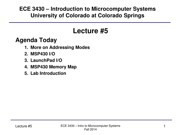
ECE 3430 – Introduction to Microcomputer SystemsUniversity of Colorado at Colorado Springs Lecture #5 Agenda Today • More on Addressing Modes • MSP430 I/O • LaunchPad I/O • MSP430 Memory Map • Lab Introduction ECE 3430 – Intro to Microcomputer Systems Fall 2014
Addressing Modes Summary As we discussed, there are only 4 fundamental addressing modes plus a few alternate uses of the original 4. In summary, this yields what you can consider 7 addressing modes: • Register Direct (*) • Single cycle • Ex: mov.w R10, R11 • Indexed (*) • Table/array processing • Ex: mov.w 2(R5), 6(R6) • Symbolic [really indexed addressing mode] • PC-relative • Ex: mov.w 1088h, 108Ah Can use “labels” here for easier code read • Absolute [really indexed addressing mode] • Directly access any memory location. • Ex: mov.w &1088h, &108Ah Can use “labels” here for easier code read ECE 3430 – Intro to Microcomputer Systems Fall 2014
Addressing Modes Summary • Register Indirect (*) • Access memory with pointers. • Ex: mov.w @R10, 0(R11) • Indirect Autoincrement (*) • Table/array processing. • Ex: mov.w @R10+, 0(R11) • Immediate (really indirect autoincrement addressing mode) • Unrestricted constant values. • Ex: mov.w #45h, &1080h Can use “labels” here for easier code read (*) = Native Addressing Mode ECE 3430 – Intro to Microcomputer Systems Fall 2014
Addressing Modes Summary Labels (discussed in detail later) can be used to refer to commonly-used constants. In a sense, they can be thought of as variable names. In the following example, I have used the variables myVar1 and myVar2 that supposedly have already been defined to live somewhere in memory: Symbolic: • Ex: mov.w myVar1, myVar2 Absolute: • Ex: mov.w &myVar1, &myVar2 Immediate: • Ex: mov.w #45h, &myVar1 ECE 3430 – Intro to Microcomputer Systems Fall 2014
Atomic Operation A single CPU instruction is “atomic”. This is a word used in computer science to mean that nothing can interrupt this instruction (except a power failure of course). Anything else that wants to happen must wait for the current instruction to complete once it is started. This is a fundamental rule in all CPU architectures! ECE 3430 – Intro to Microcomputer Systems Fall 2014
Special Immediate Values As we have seen, any constant value can be written into any memory location or CPU register using the immediate addressing mode. The immediate value cannot exceed the precision of the machine. For the MSP430, the largest unsigned value allowed is 65535 (16-bit limit). You can use signed values too. In which case, your range is limited to -32768 to +32767. Immediate values -1, 0, 1, 2, 4, 8 are generated in hardware by the constant generators (R2 and R3). The assembler does this for you behind the scenes. Doing so allows code memory to be compressed (less operands) – an estimated 30%. ECE 3430 – Intro to Microcomputer Systems Fall 2014
MSP430 Input and Output (I/O) MSP430 Ports - • There are many varieties of the MSP430—each of which can have different I/O definitions. • Our version of the MSP430 has 2, 8-bit I/O registers. Other versions may have multiple I/O registers. These I/O registers are called ports. • Ports are data latches that exist outside of the CPU core (but still inside the microcontroller). Each port is assigned a designated memory location. When a load or a store operation targets the address belonging to a port register, the data is read from or written to the data bus—reading input pins and/or adjusting the state of output pins. • Directionality of bi-direction I/O pins must be specified in a data direction control register. • I/O pins can have multiple purposes (see text book page 22 and data sheets). You may have to specify the purpose of the pin too either directly or indirectly. ECE 3430 – Intro to Microcomputer Systems Fall 2014
MSP430 Input and Output (I/O) Therefore, gathering data from an external device or writing data to an external device is accomplished by loading from and storing to dedicated memory locations. For this reason, the MSP430 uC is referred to as a memory-mapped architecture. We are using the MSP430G2 in a 20-pin DIP package. • All of port 1 and port 2 is brought out to external pins on the MSP430 (G2553) package. • If more I/O pins are required, various forms of I/O expansion logic can be added (such as shift registers or I2C-based I/O expanders). ECE 3430 – Intro to Microcomputer Systems Fall 2014
LaunchPad LaunchPad - This is the target board that the MSP430 is loaded on. The target board is a printed circuit board (PCB) that contains all of the necessary peripheral circuitry (crystal oscillator [clock], power regulators, USB interface, etc.) The LaunchPad provides: 1) Connectors for I/O and USB. 2) Power comes across the USB cable. 3) Crystal oscillator [XTAL]. 4) Voltage Regulators. 5) USB endpoint and emulation logic (used to interface to a host computer for programming and debugging). 6) A few push buttons (one is the reset button). 7) A few LEDs. See online TI pages for more information: www.ti.com/launchpadwiki ECE 3430 – Intro to Microcomputer Systems Fall 2014
MSP430 Memory Map • The MSP430 is a memory-mapped architecture—all I/O is done as though you are interacting with a memory device. • The MSP430 internal Flash (which we’ll use for program code storage) is mapped to a particular memory range. • The lower boundary varies based on the amount of Flash (non-volatile). • The upper boundary is fixed. • The MSP430 has some internal RAM (which we’ll use for program data storage) which is also mapped to a particular memory range. • The lower boundary is fixed at 0x0200. • The upper boundary varies based on the amount of RAM (volatile). ECE 3430 – Intro to Microcomputer Systems Fall 2014
MSP430 Common Memory Map ECE 3430 – Intro to Microcomputer Systems Fall 2014
MSP430 Memory Map • The interrupt vector table will be discussed in detail later. All architectures have one! At least certain parts of this vector table must be in non-volatile memory! • The 8 and 16-bit peripheral modules sections map to the on-chip peripheral devices: which are outside of the CPU—but still inside the MSP430 uC. Size of access must be correct. Grouped together to not waste memory space. • Special function registers are usually specific to the CPU. Might be used for enabling functions of some peripherals. ECE 3430 – Intro to Microcomputer Systems Fall 2014
Port I/O • For port I/O, many peripheral registers may need to be configured. Primarily PxSEL, PxDIR, PxOUT, PxIN (where x is replaced with the port number). • These names are defined by headers included by you. We use these names because they agree with convention and documentation. P1SEL: Setting pin function (for I/O and not alternate purpose) P1DIR: Defines the direction of each I/O pin (input or output) • By default, all I/O pins that have configurable direction are inputs! P1OUT: Data to be written goes here (outputs change). • No effect on input pins. P1IN: Sample I/O pins through here • Register is volatile (because external asynchronous events can change inputs). ECE 3430 – Intro to Microcomputer Systems Fall 2014
Port I/O • There are many other I/O configuration registers that may be of interest. The MSP430 architecture allows for specification of internal pull-up and pull-down resistors and interrupt use. • See the MSP430x2xx Family User's Guide link for more information. ECE 3430 – Intro to Microcomputer Systems Fall 2014
MSP430 Interaction with PC The IAR Embedded Workbench Software for the MSP430 is what we’ll be using in lab this semester. Also known as EW430 for short. This software package contains: • C/C++ compiler • Assembler • Linker • Downloader • Debugger All communication with the LaunchPad is done via USB. The textbook author discusses basically how to use the IDE in Appendix A. Your lab instructor will discuss the use of it further with you in lab. Other toolsets (such as Code Composer Essentials) can be used--but for this semester we ask that use IAR only just to keep everyone on the same page! ECE 3430 – Intro to Microcomputer Systems Fall 2014
Basic Code Development Process • Set up a workspace and project. A workspace can contain multiple projects. In this course, you’ll probably only have one project within the workspace. • Workspaces are given an EWW file extension (ex: lab1.eww). • Projects are given an EWP file extension (ex: lab1.ewp). • Write the CPU source code in language of choice using text editor. • In this class we will be writing mostly in assembly! • Source code is always “plain text” format (don’t use word processors)! • IAR uses S43 file extensions for assembly source files (ex: lab1.s43). • C source files almost universally use a C file extension (ex: lab1.c). • Upon a successful build, you will get many auto-generated files. We’ll discuss these in detail later. For now: • The R43 file (ex: lab1.r43) is an object file fed to linker. • The D43 file (ex: lab1.d43) is the executable. • The LST file (ex: lab1.lst) is a listing file (discussed later). • Download (and optionally debug) the source code using the IDE. A full-blown assembler reference guide (PDF) can be found in the EW430 Help menu. ECE 3430 – Intro to Microcomputer Systems Fall 2014
Lab Introduction For lab #1 you are wiring up (or have wired up) a fixed circuit which you will use for the rest of this semester on a breadboard. We are not concentrating on the breadboard too much this semester (take ECE 3440 if you want to interact with cooler things). This class will focus more on the internals of the MSP430. The breadboard is only there to give us some form of I/O to interact with. The LaunchPad can be interfaced to the breadboard via a ribbon cable and connectors. Power is provided to your breadboard via the ribbon cable. Never attach your breadboard to power supplies! Let the LaunchPad power the breadboard. ECE 3430 – Intro to Microcomputer Systems Fall 2014
Lab Introduction As you continue wiring up lab #1, think about the active-high and active low sensor/actuator techniques we talked about. Once you are wired up, you will run some code on the MSP430 that is already written and assembled into an executable file. You will download the binary file via the IAR tools. When the test code runs on the MSP430, it will exercise the sensors and actuators on your breadboard. This program allows you to verify that your hardware works and you didn’t make any wiring mistakes. If later in the semester you think hardware has a problem, revert back to running the pre-compiled lab 1 program. ECE 3430 – Intro to Microcomputer Systems Fall 2014
Lab Introduction Read the lab introduction section BEFORE you come to each lab this semester. Many of your questions may be answered in the introduction. The introduction will help you understand what you are doing. Your lab instructor will get irritated if you ask questions that are answered in the introduction section. To sum it up, be prepared! ECE 3430 – Intro to Microcomputer Systems Fall 2014
Practical Examples and Tips • Use the symbolic addressing mode for interacting with variables you define. • Use the absolute addressing mode for interacting with peripheral registers defined by hardware. Examples: mov.w #45h, myVar1 initializes myVar1 in RAM mov.b #45h, &P1OUT initializes output pins mov.w myVar1, myVar2 copies variables in RAM mov.w myVar1, R8 RAM to CPU register (load) mov.w R9, myVar2 CPU register to RAM (store) mov.w R6, R7 copies registers in CPU mov.b myVar2, &P1OUT causes outputs to change mov.b R8, &P1OUT causes outputs to change mov.b &P1IN, myVar1 samples inputs into RAM mov.b &P1IN, R9 samples inputs into CPU register FOR BEST PERFORMANCE, USE ALL GENERAL-PURPOSE CPU REGISTERS (R4-R15) BEFORE RESORTING TO THE USE OF RAM VARIABLES! ECE 3430 – Intro to Microcomputer Systems Fall 2014