Download
1 / 6
140 likes | 917 Views
FAMU-FSU College of Engineering Department of Civil Engineering Soil Mechanics CEG 3011 By Kamal Tawfiq, Ph.D., P.E. Fall 2007. Mohr Circle Pole Method. I. Draw Mohr Circle 1- Locate Points A & B 2- Connect Points A & B with a stright line

E N D
FAMU-FSU College of Engineering Department of Civil Engineering Soil Mechanics CEG 3011 By Kamal Tawfiq, Ph.D., P.E. Fall 2007 Mohr Circle Pole Method
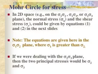
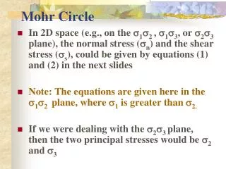
I. Draw Mohr Circle 1- Locate Points A & B 2- Connect Points A & B with a stright line 3- Line A B intersects axis Fn at the center of the circle (o) 4- Usin your Compass, draw a circle with a radius = OA. 5- Mohr circle will intersects Fn axis at pints F1 and F2. 6- F1 and F2 represent the major and minor principal stresses. 7- Determine the magnitudes of F1 and F2. Sign of Shear Stress is based on the rotation of the shear Fy Jxy +J Fx Fx Jxy (-) (+) Fy (+Fx, + Jxy) B +Jxy F2 F1 Fy Center Fn O Fx -Jxy A (+Fy, - Jxy ) Fx Fy -J
II. Establishing the Pole on the Circle 7- Determine the orintation of the plane at which + Fyand - Jxy are acting (Horizontal) 8- Draw a line from point (+Fy, - Jxy ) on Mohr Circle parallel to the plane ( // ) 9- Determine the orintation of the plane at which + Fyand + Jxy are acting (Vertical) 10- Draw a line from point (+Fy, - Jxy ) on Mohr Circle parallel to the plane (/// ) 11- Extend the two lines (//) and (///) so that they intersect on the circumference of Mohr Circle. 12- This intersection represents the POLE Fy Jxy +J Fx Fx Jxy Fy (+Fx, + Jxy) F2 F1 Fn (+Fy , - Jxy ) Pole Fx Fy -J
III. Establishing the Directions of the Principal Stresses (2) 13- From the Pole extend two lines. One through F1 and another through F2. 14- The directions of these two lines represents 2. Fy Jxy +J Fx Fx Jxy Fy Fx, Jxy F2 2 F2 F1 Fn Fy, Jxy Pole F1 Fx Fy -J
Fy F1 Jxy +J F2 Fx Fx F2 Jxy 2 F1 Fy Fx, Jxy F2 2 F2 F1 Fn Fy, Jxy Pole F1 Fx Fy -J
MohrCircle Pole Method Fy Jxy Fx +J Jxy Fn Jn (+Fn, + Jn) Fx Pole X Plane where F2 is acting 2 Fy A (+Fx, + Jxy) +Jxy F2 F1 Center Fn O -Jxy (+Fy, - Jxy ) B Plane where F1 is acting B Fx Fy -J