Download
1 / 31
320 likes | 359 Views
XTOD Attenuator Status. DOE Review of the LCLS Project (SC4) October 25, 2006. Richard Bionta, Stefan Hau-Riege, Keith Kishiyama, Donn McMahon, Marty Roeben, Dimitri Ryutov, John Trent and Stewart Shen.

E N D
XTOD Attenuator Status DOE Review of the LCLS Project (SC4) October 25, 2006 Richard Bionta, Stefan Hau-Riege, Keith Kishiyama, Donn McMahon, Marty Roeben, Dimitri Ryutov, John Trent and Stewart Shen This work was performed under the auspices of the U.S. Department of Energy by the University of California, Lawrence Livermore National Laboratory under Contract No. W-7405-Eng-48.
Content • Physics Requirements • Aperture Arrangement • Gas Attenuator • Solid Attenuator • Integrated Attenuator Design • Prototype Testing • Project Management Issues
Design based on Physics Requirements* * LCLS-PRD-1.5-003 “Physics Requirements for the XTOD Attenuator System”, 3/15/2006
Attenuator is part of Front End Enclosure (FEE) Slit Spectrometer Package Solid Attenuators Collimator 1 Total Energy Fixed Mask Beam Direction Gas Attenuator Gas Detector Gas Detector Direct Imager (Scintillator) FEL Offset Mirror System
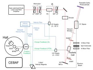
N2 boil-off (surface) Gas Detector / Attenuator Conceptual Configuration Gas detector Flow restrictor 4.5 meter long, high pressure N2 section Differential pumping sections separated by 3 mm apertures 3 mm diameter holes in Be disks allow 880 mm (FWHM), 827 eV FEL to pass unobstructed Solid attenuators N2 Gas inlet Green line carries exhaust to surface Status Attenuator: PRD done SCR done Prototype done ESD draft PDR in preparation Gas detector
Gas detectors share differential pumping with the Gas Attenuator Optical band pass filter Photo diode Gas Attenuator high pressure section Gas detector ~0.1 to 2 Torr N2 ~1 Torr ~10-3 Torr ~10-3 Torr ~10-6 Torr 20 Torr ~20 cm inner diameter non-specular reflective surface (e.g. treated Al) Single shot, non destructive, measurement of u 2 m Optical ND filters Photo tube LCLS X rays cause N2 molecules to fluoresce in the near UV
3-mm Apertures in Transition Stages with Bellows to allow transverse positioning of opening in window Be disk on gate valve survives FEL hits. Disks are transparent to high energy spontaneous, allowing alignment of hole using WFOVDI camera in FEE. Gate valve removes window when gas attenuator not in use and for ease of alignment.
Alignment concept using direct imager Gas Detector 1 Gas Detector 2 Gas Attenuator ~10-6 Torr ~10-6 Torr 2 Torr 2 Torr 20 Torr 10 cm 4.5 m 10 cm 2 m 2 m WFOV Direct Imager 1.5 m 1.5 m
Open valves to align sections Gas Detector 1 Gas Detector 2 Gas Attenuator ~10-6 Torr 0.7 Torr 0.7 Torr 20 Torr 10 cm 4.5 m 10 cm 2 m 2 m WFOV Direct Imager 1.5 m 1.5 m
Low energy spontaneous through attenuator windows (40 mm diameter x 1 mm thick with 3 mm diameter hole through center) 1 window with Ta ring 3 windows with Ta rings 1 window 10 cm 10 cm 3 mm hole may be hard to see (limited by simulation statistics) but Ta rings allow easy identification of hole position
Direct imager image of saturated low energy FEL + Spontaneous 3 valves closed 4.6 mR + 6 mm misalignment 3 valves closed 0.46 mR + 300 mm misalignment All valves open With this method it is easy to locate the FEL and systematically align the apertures with the FEL whereverit is located
Attenuator Risks and Mitigations • Pressure calculations, and system stability (pumping, temperature, flow) • Retired. Proved by prototype testing results. • Accuracy & Repeatability Unachievable • Repeatability proven. • Accuracy within 5% likely achieved, assuming local temp fluctuation is negligible. • Possible Optical Distortion caused by gas plume disturbance • Calculation shows it is not a problem. • Contribution of the transition stages to uncertainties in the attenuation • In PDR, shorter transition stages will be pursued. • Corrosion of the Be by the N2 gas or ions • This could be a problem, Ar gas is the alternative, or replace the Be with B4C.
Prototype Integrated Attenuator System Gas Attenuator Gas Detector Cell
Gas Detector Cell Last Stage (Stage 6)
Completed Prototype System @ LLNL Vacuum Lab Gas Flow Control-1 Gas Flow Control-2 Gas Attenuator Gas Detector Cell Last Stage
Integrated System Vacuum Modeling Normal Operation Gas Attenuator 20 Torr Gas Detector 2.5 Torr Pressure Distribution Attenuator Pressure 20 Torr V-2 1.02 Torr V-3 1.86x10⁻³ Torr V-4 (GD) 2.0 Torr V-5 4.74x10⁻³ Torr V-6 3.55x10⁻⁶ Torr Qi 1506 sccm Qg 171 sccm RESULTS In response to step gas inputs of Qi and Qg,, 1.Attenuator pressure reached design level (20 Torr) 2.Gas detector pressure reached design level (2.0 Torr) 3. Last stage pressure met boundary conditions (~3x10⁻⁶ Torr)
Integrated System Vacuum Modeling Stand-by Operation Gas Attenuator 0 Torr Gas Detector 2.5 Torr Pressure Distribution Attenuator Pressure 1.95x10⁻⁴ Torr V-2 7.5x10⁻⁵ Torr V-3 6.6x10⁻⁴ Torr V-4 (GD) 2.0 Torr V-5 4.74x10⁻³ Torr V-6 3.55x10⁻⁶ Torr Qi 0 sccm Qg 171 sccm RESULTS In response to sudden drop of gas input of Qi,, 1.Attenuator pressure was lowered to ZERO level (10-4 Torr) 2.Gas detector pressure maintained at design level (2.0 Torr) 3.Last stage pressure still met boundary conditions (~3x10⁻⁶ Torr)
Prototype Tests (10/10/06) Pressures of Gas Attenuator and Gas Detector can be operated independently.
Comparison of Measurement & Calculation * Pump Speed S(p) was extrapolated from catalogue values
Purpose of Solid Attenuator • Attenuates high energy x-rays from to levels of current x-ray sources • Diagnostics may not be damaged • Experiments may be performed without damage • Attenuates x-rays whose energy is too high for gas attenuator to attenuate to level desired • Works in series with gas attenuator – effects may be superposed • Overlaps in attenuation levels with gas attenuator to allow large dynamic range with fine levels
Solid Attenuator Concept Overview • 64 attenuation levels • Six highly polished Be slides • Each twice as thick as the last (0.5 to 16 mm) • Up to 2,300x attenuation of 8.26 keV x-rays • Millions of attenuation levels when used with gas attenuator • Pneumatically actuated
Front View – Attenuating Pneumatic Actuator Custom Vacuum Vessel Adapter Flange Attenuator Block Attenuator Block Holder
How Solid and Gas Work Together • For 8.26 keV x-rays the range of the gas attenuation with Nitrogen at 0 to 30 Torr is 86.7% to 100% transmission • The thinnest solid attenuator (0.5 mm) at 8.26 keV provides 87.6% transmission • Overlap means gas fills in between solid levels – very fine resolution and large range
What if maximum Gas Pressure is 20 Torr? • If maximum pressure is 20 Torr there will be small gaps in achievable transmission levels • At 2 keV – No gaps from 100 to 0.1% • At 3 keV – 11.7 to 9.1%, 1.06 to 1.0%, etc. • At 4 keV – 40.6 to 36.7%, 14.9 to 14.5%, etc. • All requirements are met – at least 3 steps per decade (8 desired) • 30 Torr operation will be explored
Solid Attenuator Actuator Prototype • Measured angular repeatability of face of test block using CMM • Repeats within 0.2 deg. • 2.2 degrees required • Will repeat within 0.1% of attenuation level • 5% required Actuator Test Block CMM Probe
XTOD Attenuator Subsystem Schedule • System Concept Review (4/06) • Prototype Testing Results (10/06) • ESD (10/06) • Preliminary Design Review (12/06) • Final Design Review (3/07) • Procurement (6/07) • Assemble/Test (9/07) • FEE Beneficial Occupancy (11/07) • Operational (2/08)
Summary • Integrated Attenuator System design is workable and offers numerous advantages. • Risk areas are identified. • Obtained excellent prototype testing results. • Vacuum computer modeling yields satisfactory results. • No technical problems are foreseen. • Project schedule meets current program plan.