Download
1 / 75
970 likes | 1.51k Views
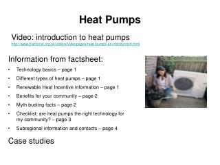
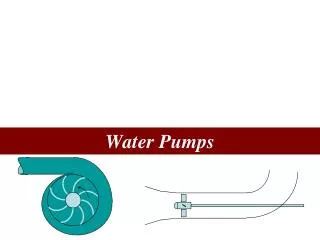
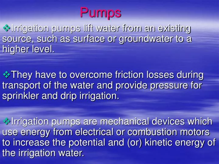
Pumps. Irrigation pumps lift water from an existing source, such as surface or groundwater to a higher level. They have to overcome friction losses during transport of the water and provide pressure for sprinkler and drip irrigation.

E N D
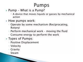
Pumps Irrigation pumps lift water from an existing source, such as surface or groundwater to a higher level. They have to overcome friction losses during transport of the water and provide pressure for sprinkler and drip irrigation. Irrigation pumps are mechanical devices which use energy from electrical or combustion motors to increase the potential and (or) kinetic energy of the irrigation water.
……Pumps Pumps are used in irrigation systems to impart a head to the water so it may be distributed to different locations on the farm and used effectively in application systems. The key requirement in pump selection and design of pump systems for typical irrigation installations is that there is a correspondence between the requirements of the irrigation system and the maximum operating efficiency of the pump. Requirements of irrigationsystem are: - flow rates - pressure out put necessary to operate the system.
Principles of Water lifting • Direct lift (Direct lift devices) physically lifting water in a container • Displacement (Displacement pumps) This involves utilizing the fact that water is (effectively) incompressible and can therefore be 'pushed' or displaced. - Rotary positive displacement pumps, which use gears, vanes, lobes or screws to move, discrete quantities of water from the inlet to the outlet of the pump. - Reciprocating positive displacement pumps: piston pumps, plunger pumps, diaphragm pumps.
Gravity (Gravity Device) – Gravity operated systems, Siphons 4. Creating a velocity head (velocity pumps • Rotodynamic pumps: volute centrifugal pumps, turbine centrifugal pumps, regenerative centrifugal pumps.
Types of pumps • Pumps used in irrigation systems are available in a wide variety of pressure and discharge configurations. • Pressure and discharge are inversely related in pump design , so pumps which produce high pressure have relatively small discharge and vice versa. Characteristics of centrifugal , turbine and propeller pumps is given as below.
Impeller design and pump characteristics as function of specific speed
In the above figure, • Flow enters the pump from the bottom. • In centrifugal pump , energy is imparted to the flow by the impeller which directs the flow radially outward. • Centrifugal pumps have high heads but limited discharge. • Francis impeller – deliver intermediate flow rates but there is less energy available to pressurize the fluid. • Propeller type system is able to deliver large flow volumes but is capable of imparting a very small pressure differential to the fluid.
Specific Speed - Ns • Means of quantitatively categorizing the operating characteristics of a pump. Where: Ns = specific speed , dimensionless N = Revolutionary speed of pump , rpm Q = Pump discharge , L /min H = discharge pressure head , m
Ns varies from 500 (centrifugal pump) to 10, 000 (propeller pump). • The Ns of a pump is closely related to the maximum operating efficiency of the pump. • Operating efficiency : ratio of the power imparted by the impeller to the water compared to the power supplied to the pump by the motor. • The performance curve indicates that careful attention must be given to the discharge requirements of the pump , which determine the specific speed, so the most suitable pump may be selected.
1. Reciprocating positive displacement pumps • use back and forth movement of mechanical parts • Water is for most practical purposes incompressible. Consequently, if a close fitting piston is drawn through a pipe full of water, it will displace water along the pipe. • Similarly, raising a piston in a submersed pipe will draw water up behind it to fill the vacuum which would otherwise occurs. • Basic relationships between the output or discharge rate (Q), piston diameter (d), stroke or length of piston travel (S), number of strokes per minute (n), and the volumetric efficiency, which is the percentage of the swept volume that is actually pumped per stroke ( η vol )
Swept area of the piston is A = The swept volume per stroke will be V= AS The discharge per stroke will be q = V η vol The pumping rate (per minute) is Q = nq
2. Rotary positive displacement pumps • These are group of devices which utilizes the displacement principle for lifting or moving water, but which achieve this by using a rotating form of displacer (gears, vanes, lobes or screws). • use gears and vanes to move discrete part of water. • These generally produce a continuous, or sometimes a slightly pulsed, water output these pumps tend themselves readily to mechanization and to high speed operation than reciprocal displacement pumps.
3. Rotodynamic (centrifugal) pumps • use the centrifugal force of rotating devices (called impellers) to increase the kinetic and pressure energy of the water. • Depends on propelling water using a spinning impeller of rotor. • There are two main types of rotodynamic pumps (centrifugal pumps), i.e. • Volute centrifugal pumps • Turbine centrifugal pumps
Reciprocating and rotary pumps are called positive displacement pumps, while centrifugal pumps are called variable displacement pumps in which the delivery head varies with the quantity of water pumped.
PUMPING THEORY-CENTRIFUGAL PUMPS • In centrifugal pumps the energy is imparted to the water by a unit of rotating vanes called an impeller, which are located in a stationary body called the casing. CASING Water is pushed into the center or eye of the impeller by atmospheric or water pressure and set into a rotary motion by the impeller. -The rotating movement causes a centrifugal force to act upon the water, which drives the water outward, between the vanes of the impeller, into the surrounding casing from where it moves to the pump outlet. -Different types of casing: a)Single volute, (b) Double volute, and (c). Diffuser turbine casing.
IMPELLERS • Impellers can be classified according to the direction of flow through the impeller in relation to the axis of rotation as (a) radial, (b) axial or (c) mixed flow. • Where high flows at low heads are required (which is common with irrigation pumps), the most efficient impeller is an axial flow one. • Impellers can also be classified according to their design into (a) open (consist only vanes attached to the hub with out shroud/side-wall), (b) semi-open (have one shroud) and (c) enclosed (have shrouds (sidewalls) enclosing the waterways between vanes) impellers as shown in figure.
CENTRIFUGAL PUMP PERFORMANCE • Pumping capacity, pumping head, power, efficiency and net positive suctionhead are the main parameters, which describe the performance of a pump. 1.Pump capacity: The capacity of a pump is the volume of water (Q) which the pump can deliver per unit of time, e.g. in litters per second (lt/s) or cubic meters per hour. 2. Pumping Head The actual pumping head imposed on a pump, gross working head, will be somewhat greater than the actual vertical distance, or static head, water has to be raised.
The pumping head (H) is the net work done on a unit of water by the pump. It is expressed by the Bernoulli’s equation. • H = (p/(g) + V2/(2g) + Z)d - (p/(pg) + V2/(2g) + Z)s P = Water pressure in (kpa or meters water column) = density of the fluid in (kg/m3) g = acceleration due to gravity in (m/S2) V = Water velocity in (m/s) Z = Elevation head in meters relative to a reference level or datum. g = =specific weight of the fluid (kN/m3)
Power • The amount of energy (in joule) applied per unit of time (seconds) is the power imparted to the water in joule/ second = Watt. Phydr = g H Q = Phydr=hydraulicor water power in Watt. Q = pumped volume in m3/s. • Pumping at a rate of 180m3/ h at a head of 120 meters require: Phydr = 1000 x 9.81 x 120 x 180/3600 = 4, 905 watt = 4.9 kw
Pump Efficiency The actual power and energy needs are always greater than the hydraulic energy needed • Therefore, the pump efficiency (pump) is the percent of power input by a motor (in kw) to the pump shaft (the so-called brake power) which is transferred to the water: hydr = (Phydr / Pmotor)x 100 hydr = pump efficiency Phydr = water power (kw, hp) Pmotor = break power (kw, hp)
Pump Power Requirements • The power added to water as it moves through a pump can be calculated with the following formula: WHP = Q x TDH 3960 where: WHP = Water Horse Power Q = Flow rate in gallons per minute (GPM) TDH = Total Dynamic Head (feet)
Break Horse power BHP = WHP Pump Eff. x Drive Eff. BHP -- Brake Horsepower (continuous horsepower rating of the power unit). Pump Eff. -- Efficiency of the pump usually read from a pump curve and having a value between 0 and 1. Drive Eff. -- Efficiency of the drive unit between the power source and the pump. For direct connection this value is 1, for right angle drives the value is 0.95 and for belt drives it can vary from 0.7 to 0.85.
Net Positive Suction Head- NPSH • The net positive section head (NPSH) is the amount of energy required to prevent the formation of vapor filled cavities within the eye of the single and fires stage impellers. • This cavities which form when pressure within the eye drop below the vapor pressure of water collapse within higher-pressure areas of the pump. • The formation and subsequent collapse of these vapor filled cavities is called cavitation. • When cavities collapse occur violently at interior surfaces of the pump they produce ring-shaped indentations in the surface called pits. Continued pitting severely damage pumps, and must be avoided
The NPSH required to prevent cavitation is a function of pump design and is usually determined experimentally for each pump. • Cavitation is prevented when heads (available NPSH) within the eye of single and first impeller exceeds the NPSH, value published by the manufacturers. • The available NPSH is a function of the atmospheric pressure, vapor pressure, friction loss, suction head and should always exceed the NPSH specified by the pump manufacturer with at least 0.5 to 1.0 meters of head.
NPSH = Ha - Hs - Hf –Hvp Ha = atmospheric pressure on the surface of the water (in m) Hs = elevation of the water above or below the impeller eye while pumping (in m) (if the level is above the eye, Hs is positive, if the level is below the eye, Hs is negative) Hf = friction-head losses in the suction piping (in m) Hvp = Vapor pressure of the water at the pumping temperature (in m). • The vapor pockets, which form when pressures within the eye of the impeller drop below the vapor pressure of the water, subsequently collapse violently within the high pressure areas of the pump. • This collapse is called cavitation and can cause severe damage to the pump. Operate the pump with in its design capacity.
PERFORMANCE CURVES • Head versus pump capacity. • Efficiency versus pump capacity. • Brake power versus pump capacity. • NPSH versus pump capacity.
AFFINITY LAWS • The performance of a pump varies with the speed at which the impeller rotates. Theoretically, varying the pump speed will result in changes in flow rate, TDH and BHP according to the following formulas: • For a constant Diameter Q2= Q1 x (N2/N1) H2 = H1 x (N2/N1) 2 BP2= BP1 x (N2/N1) 3 NPSH2 = NPSH1 x (N2/N1) 2
……Affinity Laws For constant N ( Rotation per minute) Q2 = Q1 x (D2/D1) H2 = H1 x (D2/D1) 2 BP2 = BP1 x (D2/D1) 3 NPSH2 = NPSH1 x (D2/D1)2
where Q = discharge N=number of Revolution per minute BP = Break power NPSH = Net positive suction head D = diameter H = Available head
Pump operation point • A centrifugal pump operates at combinations of head and discharge according to its H-Q characteristic performance curve. The particular combination of H-Q at which a pump is operating is the pump’s operating point. Power requirement, efficiency and NPSH for the pump can be determined once the operating point is known. • The specific operating point depends on the head and water volume requirements of the irrigation system. A system curve describes the H–Q performance of the irrigation system. • The system curve is then combined with the H-Q characteristic curve of the pump to determine the operating point.
….Pump operation point • Operating points can be altered by changing either the H-Q curve for the pump or for irrigation system. Pump can be altered by changing the pump speed or the impeller diameter (see the Affinity Laws).
Pump curve for 2000rpm H Pump curve for 1800 rpm Pump operation point Q Shifting pump operation point This is the point where the H-Q requirements of the irrigation system are equal to the H-Q produced by the pump.
The system curve is constructed by calculating the system head Hs required by the irrigation to deliver varying volumes of water per unit of time. • The system head Hs is calculated with the formula Hs = SL+ DL+ DD+ H1 + M1 +HO + VH Where: HS = System head (m) SL = Suction lift from static water level (m) DL = discharge lift from pump to highest discharge point (m) DD = draw down in water source (m) H1 = head loss in delivery pipes (m) M1 = minor losses in fittings (m) Ho = operating head (m) VH = velocity head (m)
Total Dynamic Head • The total dynamic head of a pump is the sum of the total static head, the pressure head, the friction head, and the velocity head. TDH =Z +Hs + hv + hf • Total Static Head • The total static head is the total vertical distance the pump must lift the water. When pumping from a well, it would be the distance from the pumping water level in the well to the ground surface plus the vertical distance the water is lifted from the ground surface to the discharge point. When pumping from an open water surface it would be the total vertical distance from the water surface to the discharge point.
Water Horse Power (WHP) WHP = Q H WHP = the energy pump produces to move the water BHP = Input power to the pump given by the motor = out put of the motor Input power for the motor is from electricity. P = Q H Sg 4634 E Where: P = power , metric horse power Q = Pump discharge, L/min H= Discharge pressure head, m Sg =specific gravity of fluid, dimensionless E = pump efficiency , fraction
Where Q = m3/hr P = Q H Sg 278.04 E P = Q H Sg 0.102 E Where P = power , KW Q = discharge , m3/s P = Q x TDH Sg 3960 E Where P = power, brake horse power (bhp) Q = pump discharge , (gpm) TDH or H = Discharge pressure head , ft
input BHP Motor Pump WHP Em Ep EPP Water Horse Power (WHP) WHP = Q H WHP = the energy pump produces to move the water BHP = Input power to the pump given by the motor = out put of the motor Input power for the motor is from electricity.
Pump efficiency Ep = WHP /BHP Em = BHP/ input EPP = WHP/ input = Ep . Em Where Em = Efficiency of motor Ep = efficiency of pump EPP = Efficiency of pumping plant
Combination of pumps • Pumps in parallel - To provide more Q and not more head Q = Q1 + Q2 + Q3 Q P2 P3 P1 Q2 Q1 Q3 River