Download
1 / 14
210 likes | 661 Views
Conducted Emissions and Susceptibility. Conducted emissions are simpler to investigate than radiated emissions because only the product’s power cord needs to be measured. Measurements of conducted emissions are made using a l ine i mpedance

E N D
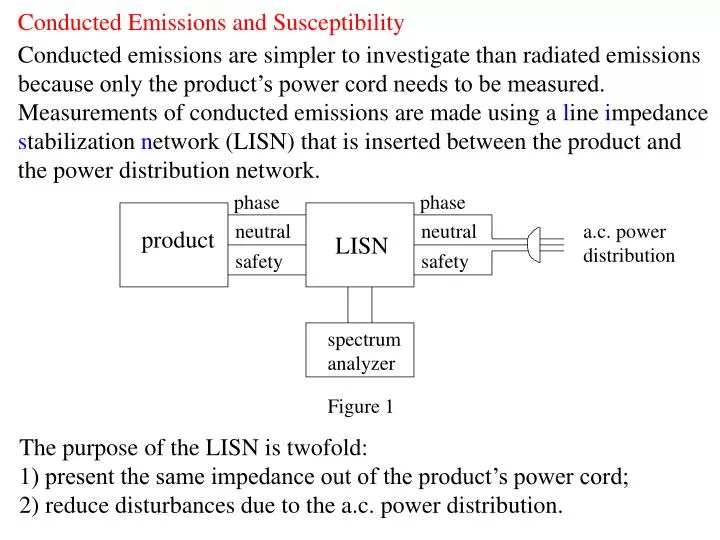
Conducted Emissions and Susceptibility Conducted emissions are simpler to investigate than radiated emissions because only the product’s power cord needs to be measured. Measurements of conducted emissions are made using a line impedance stabilization network (LISN) that is inserted between the product and the power distribution network. phase phase neutral neutral a.c. power distribution product LISN safety safety spectrum analyzer Figure 1 The purpose of the LISN is twofold: 1) present the same impedance out of the product’s power cord; 2) reduce disturbances due to the a.c. power distribution.
The LISN used for FCC conducted emission tests is: phase 50H LISN neutral 50H Product 1F 1F 1F + + 50 1k 1k 50 Dummy load receiver - - green wire Figure 2 The values of the inductors and the capacitors are chosen so that in the frequency range of interest the inductors have a large impedance and the capacitors are almost short circuits.
In this way, the phase current and the neutral current are related to the voltages by: Note that for the CISPR 22 conducted emission test, the frequency range is different (150 KHz-30 MHz) and both capacitors and inductors must have other values to obtain the desired behavior.
Common Mode and Differential Mode Currents The simplified representation of a LISN as two 50 resistor is the following: phase neutral 50 50 Green wire Figure 3 and, similarly to what we did for the radiated emissions, we introduce common and differential mode currents as:
In the case of conducted emissions, common mode currents can be of the order of differential mode currents. If this is the case, then and are different since they are given by: Usually one component dominates the other so that the magnitudes of and are the same. Conducted emissions are usually reduced by introducing a power filter. A power filter contains elements each one of them reducing either common or differential mode currents
An usual way to block common mode currents is the green wire inductor: phase Product neutral Green wire Figure 4 Other ways of reducing emissions are considered in the following. We want to remind that almost all electronics products contain some form of power filter where the power cord exists the product. Sometimes the filter is simply a large transformer or a linear power supply that provide inherent filtering; for all other cases an “intentional” power filter is required.
A typical topology of a power supply filter is shown in the following: Figure 5 : green wire inductor - blocks common mode currents; : divert differential mode currents - these are line-to-line capacitors or X caps; : divert common mode currents - these are line-to-ground capacitors or Y caps; L, L: two coupled inductors -- block common mode currents
The purpose of the filter is to reduce so that: are below the limits.
Let us consider the operation of the power supply filter when only common mode currents are present: Figure 6 Common mode currents are represented with current sources. Because of the symmetry of the circuit, we obtain the equivalent model: L+M Figure 7 Note: the common mode choke appears as an inductance L+M, and the green wire inductor appears doubled because the current through it is doubled
The operation of the power supply filter under differential mode currents is understood by considering the following: Figure 8 Again, in this case, differential mode currents are represented with current sources; due to the symmetry of the circuit we obtain the equivalent representation: L-M Figure 9 Note: line to line capacitors appear twice as large to differential mode currents; line to ground capacitors also affect differential mode currents. In the ideal case, L-M=0 and differential model currents are completely blocked.
Separation of common mode and differential mode currents The actual behavior of a power supply filter is not the ideal one and in a practical situation the conducted emissions may behave as in the following: Figure 10 The total current is given by: (9) And when one of the components ( ) is much larger than the other. The total current is dominated by the larger component.
Therefore, in order to reduce the total emissions, one should identify (in a given frequency range) the dominant current component and change the elements of the power supply filter to reduce its emissions. The common mode and differential mode components are identified via a diagnostic tool, such as the one shown in the following: Figure 11
Additional considerations Even with the use of power supply filters, only a certain degree of emission reduction can be accomplished. In general, the best way to suppress conducted emissions is to reduce them at their source. However, this is not always possible, as in the case of the noise due to sharp rise and fall times of clock waveforms For example, the switched-mode power supplies that are found in many products are generally the leading cause of conducted emissions. The operation of these power supplies relies on short rise/ fall times in order to increase the energy conversion efficiency. Another simple way to reduce conducted emissions is based on the appropriate location of the power supply and the power filter.
Let us consider the two following configurations: Internal fields Internal fields Power Supply Power Supply Filter Filter Product cabinet Product cabinet (b) (a) Figure 12 Case (a) represents a poor choice for the location of the filter and the power supply because the fields inside the product cabinet may couple with the wires that lead to the power cord. Case (b) shows the proper location of both the filter and the power supply. In this way, the emissions transmitted to the power cord are reduced to minimum level provided by the filter. In general, the filter should be placed against the cabinet to minimize the coupling with the internal fields. For the same reason, the power supply should go as close as possible to the filter.