Download
1 / 22
250 likes | 287 Views
Schematic Symbols. The Key to Understanding Wiring Diagrams. Battery. Supplies a Direct Current (DC) source. Resistor. Resistors impede the flow of electricity. SPST Switch (Single Pole Single Throw). Opens (off) or closes (on) an electrical circuit.

E N D
Schematic Symbols The Key to Understanding Wiring Diagrams
Battery Supplies a Direct Current (DC) source
Resistor Resistors impede the flow of electricity
SPST Switch (Single Pole Single Throw) Opens (off) or closes (on) an electrical circuit
SPDT Switch (Single Pole Double Throw) Switches from one electrical circuit to another
Light Bulb Converts electricity into light
Fuse Only allows a predetermined amount of current (AMPS) to pass through and if that amount is exceeded it will melt in half (open)
Capacitor Blocks Direct Current (DC) flow, but allows Alternating Current (AC) to pass through
Diode/Rectifier Allows current to flow through only one direction
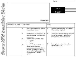
Transistor A solid-state electronic device that is used to control the flow of electricity in electronic equipment and usually consists of a small block of a semiconductor (as germanium) with at least three electrodes
Motor Converts electrical energy into motion
Electric Fuel Pump FP A motor driven pump, which supplies fuel to the engine
Chassis Ground Connects the circuit to the metal body or frame of the vehicle using the body as a conductor in the circuit
Ground Connects the circuit to the metal body or frame of the vehicle using the body as a conductor in the circuit (More commonly used than chassis ground)
Relay OR An electromagnetically controlled switch
Electromagnet Becomes magnetic when Direct Current (DC) is passed through it
Light Emitting Diode A one-way check valve for electricity that lights up when current is passing through
Variable Resistor The resistance to the flow of electricity can be adjusted
Variable Capacitor A variable capacitor is a capacitor whose capacitance may be intentionally and repeatedly changed mechanically or electronically. Variable capacitors are often used in L/C circuits (tuners) to set the resonance frequency, e.g. to tune a radio (therefore they are sometimes called tuning capacitors)
Transformer/Coil The secondary induced voltage VS is scaled from the primary VP by a factor ideally equal to the ratio of the number of turns of wire in their respective windings: • By appropriate selection of the numbers of turns (N), a transformer thus allows an alternating voltage to be stepped up — by making NS more than NP — or stepped down, by making it less.
Rotary Switch Multi-position switch like the one used in the DVOM!
Horn/Speaker Converts electrical energy into sound