Download
1 / 25
250 likes | 257 Views
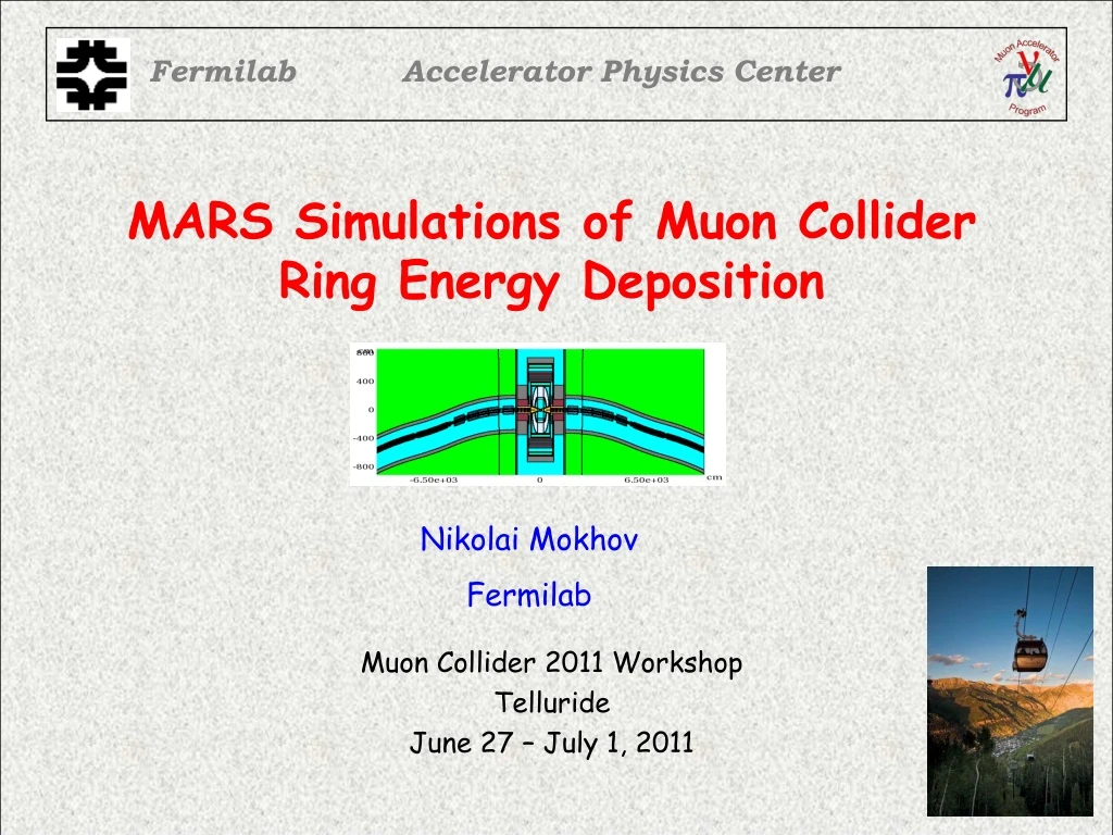
Fermilab. Accelerator Physics Center. MARS Simulations of Muon Collider Ring Energy Deposition. Muon Collider 2011 Workshop Telluride June 27 – July 1, 2011. Nikolai Mokhov Fermilab. OUTLINE. Sources and Radiation Issues MARS15 Modeling Recent Improvements Tagging Source

E N D
Fermilab Accelerator Physics Center MARS Simulations of Muon ColliderRing Energy Deposition Muon Collider 2011 Workshop Telluride June 27 – July 1, 2011 Nikolai Mokhov Fermilab
OUTLINE • Sources and Radiation Issues • MARS15 Modeling • Recent Improvements • Tagging Source • Power Density and Heat Load Distributions • Summary Energy Deposition in MC Ring - N.V. Mokhov
Muon Collider Ring Parameters Energy Deposition in MC Ring - N.V. Mokhov
Source of Radiation Loads: Muon Beam Decays • Electromagnetic showers, induced by energetic electrons (1/3 of muon’s E) and synchrotron photons in the collider components, result in high radiation levels in the storage ring. • For 0.75-TeV muon beam of 2x10¹²: 4.28x10⁵ dec/m per bunch crossing, or 1.28x10¹⁰ dec/m/s for 2 beams. • This corresponds to 0.5 kW/m in electrons and almost all of this power is deposited in lattice components. • Compare this to ~2 W/m in hadron collider SC rings, and ~10 W/m in their final focus regions. Energy Deposition in MC Ring - N.V. Mokhov
Radiation Issues in MC SC Magnets • Quench stability: peak power density and heat transfer • Dynamic heat loads: cryo plant capacity and operational cost • Radiation damage: Component lifetime • Residual dose rates: Hands-on maintenance Energy Deposition in MC Ring - N.V. Mokhov
MARS15 Modeling • Detailed magnet geometry, materials, magnetic fields maps, tunnel, soil outside and a simplified experimental hall plugged with a concrete wall. • Detector model with Bz = 3.5 T and tungsten nozzle in a BCH2 shell, starting at ±6 cm from IP with R = 1 cm at this z. • 750-GeV bunches of 2×10¹²m- and m+ approaching IP are forced to decay at |S| < Smax, where Smax up to 250 m at 4.28×10⁵ / m rate, 1000 turns. Plus regular arcs. • All physics processes included. • Cutoff energies optimized for materials & particle types; in arcs: 0.001 eV (n) and 0.2 MeV (others). Energy Deposition in MC Ring - N.V. Mokhov
Energy Deposition in IR Dipoles Dynamic heat load:200 W/m in W-rods, and 245 W/m in cold mass The open midplane design for the dipoles provides for their safe operation. The peak power density in the IR dipoles is about 2.5mW/g, below the quench limit for the Nb3Sn superconductor based coils at the 1.9-K operation. Energy Deposition in MC Ring - N.V. Mokhov
Ring Dipole Magnets Nb3Sn dipole coils are arranged in a shell-type configuration. The coil aperture is 80 mm, the coil to coil gap is 30 mm with two 3-mm wide AlBemet spacers. Magnetic length is 6 m, straight (RBEND). The nominal field is 10 T. Energy Deposition in MC Ring - N.V. Mokhov
Recent Improvements and Studies • Optimized tungsten masks between each magnet element • 7.5-mm tungsten liner in quad aperture • Two 3×30 mm AlBemet spacers in open midplane dipoles • Tagging energy deposition in dipoles • Thorough study of dynamic heat loads in lattice components Energy Deposition in MC Ring - N.V. Mokhov
Fragment of Ring Model Quad Dipole Magnet local coordinate system W masks D21 D22 Energy Deposition in MC Ring - N.V. Mokhov
Ring Dipole and Tungsten Mask 2×4cm L=20cm, R=15cm Albedo trap in water-cooled W-rods; two 3×30mm AlBemet spacers Energy Deposition in MC Ring - N.V. Mokhov
Ring Quadrupole 7.5-mm W liner Energy Deposition in MC Ring - N.V. Mokhov
m+ Beam Decays (1) Horizontal Magnet local coordinate system Ring outside Energy Deposition in MC Ring - N.V. Mokhov
Source Asymmetry & Energy Deposition Decay electrons are swept toward the ring center, heating mainly inward magnet components, but outward parts are also irradiated at a few % level. Open geometry and magnetic field of open mid-plane dipole further enhance later spread of electromagnetic showers towards more symmetric transverse profile of energy deposition in magnet. Peak energy deposition in the inward W-rod is 100 times higher than in the outward one. Energy Deposition in MC Ring - N.V. Mokhov
m+ Beam Decays (2) Magnet local coordinate system Vertical Ring outside Energy Deposition in MC Ring - N.V. Mokhov
Tagging for m+ Beam Main contribution to energy deposition in arc dipole SC coils: 22% from 100-400 GeV e+ and 39% from >400 GeV e+. Remainder is distributed rather uniformly between other energies and other particles. Energy Deposition in MC Ring - N.V. Mokhov
Power Density Isocontours in Ring: m+ Beam Horizontal Magnet local coordinate system Ring outside Energy Deposition in MC Ring - N.V. Mokhov
Power Density Isocontours in Ring: m- Beam Horizontal Magnet local coordinate system Ring outside Energy Deposition in MC Ring - N.V. Mokhov
Power Density Isocontours in Ring: Two Beams Magnet local coordinate system Horizontal Ring outside Energy Deposition in MC Ring - N.V. Mokhov
Power Density Isocontours in Ring: Two Beams Magnet local coordinate system Vertical Energy Deposition in MC Ring - N.V. Mokhov
Power Density Isocontours in Ring Dipole Ring outside Peak in SC: 1.2 mW/g safely below quench limit Energy Deposition in MC Ring - N.V. Mokhov
Power Density Isocontours in Ring Quad Ring outside Peak in SC: 1.2 mW/g, safely below quench limit It was ~30 mW/g in old configuration Energy Deposition in MC Ring - N.V. Mokhov
Dynamic Heat Loads to Arc Components With a high accuracy, mean in the arc = 0.5 kW/m Averaged over corresponding component types (W/m): • Comments • Dipole: “cold” = 15 (coils+collar+spacers) + 10 (yoke) • Dipole: “room temp” is 40-mm OD W-rods • Quad: “room temp” is 7.5-mm W-liners • Mask: “D/Q” - between dipole and quad • Mask: “D/D” – between two dipoles Energy Deposition in MC Ring - N.V. Mokhov
Residual Dose Isocontours in Dipole & Quad Peak on outside = 0.5mSv/hr: at least 100 times less of that at LHC Energy Deposition in MC Ring - N.V. Mokhov
Summary • Source term for energy deposition in arc magnets is well understood. • Peak power density in ring magnets can be reduced safely below the quench limit with a proposed mask/liner protection system. • With that system, dynamic heat loads to ring dipole cold mass can be reduced to a 5% level, from 500 to 25 W/m; the later is not that far from the LHC IR levels at nominal and, certainly, at upgrade luminosities. • Radio-activation of arc magnets is substantially lower than at LHC. Energy Deposition in MC Ring - N.V. Mokhov