Download
1 / 57
570 likes | 715 Views
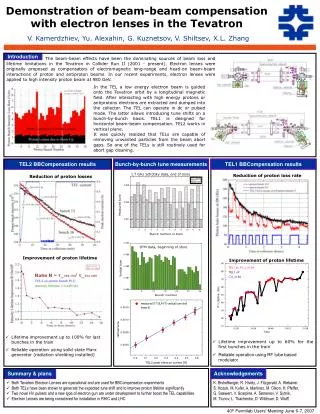
Two-dimensional and wide dynamic range profile monitor using OTR/fluorescence screens for diagnosing beam halo of intense proton beam Y. Hashimoto, T. Toyama, T. Mitsuhashi and M. Tejima KEK. In The J-PARC, We want to see beam profile of proton beam (like in the electron machine).

E N D
Two-dimensional and wide dynamic range profile monitor using OTR/fluorescence screens for diagnosing beam halo of intense proton beam Y. Hashimoto, T. Toyama, T. Mitsuhashiand M. Tejima KEK
In The J-PARC, We want to see beam profile of proton beam (like in the electron machine). We want to see halo profile. What is effect of beam collimator?
J-PARC 3-50 beam transportline ~ 122m Beam collimator Location of the monitor
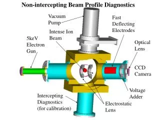
Optical design for OTR profile monitor in beam transportlinebetween 3.5GeV Rapid Cycle Synchrotron and 50GeV main ring The beam size of proton beam is 5cm! *2 dimensional charge distribution *3 dimensional charge distribution Tomographycobservation *2 dimensional halo distribution Light source is OTR and fluorescence screen 5cm
Beam halo observation by screen with hole OTR screen for beam core observation! Beam core Beam halo
Beam halo observation by screen with hole OTR from beam halo only! Beam core screen with hole Beam halo
Fluorescence screen for observation of beam halo in outside Beam halo observation by screen with hole Beam core
OTR : 3GeV ProtonBeam(Low γ) 2.5×10¹⁰ photons/1013 protons g = 32 at 30GeV g = 4.2 Intensity : Emitted photon number in a light band (w2-w1)
RCS 3GeV PS 12GeV Angular distribution of OTR from 3.5GeV Al foil target and proton beam Peak is in 350mrad!
OTR screen 45º Large field depth by large object few mrad lens Imaging device Typical OTR profile monitor at electron machine
Toyoda, Mitsuhashi 2009 for slow extraction line at J-PARC Large field depth by large object 6000mm 300mm OTR screen 45º 50 mrad Imaging device
Large field depth by large object 500mm 500mrad 45degree set up of target will impossible! Too long field depth!
500mm beam 500mrad Foil target must be normal to the beam!
Offner relay system Proton beam 500 mrad Spherical 2ed mirror D=200mm R=250mm Spherical 1st mirror D=600mm R=500mm D=300mm2枚
Application of Offner relay system to reflective input optics for the Streak camera (2002)
Design of Offner relay system General aperture 300mm Object size: 50mm
First mirror Spherical concave 300mm in diameter f=500mm Second mirror Spherical convex 200mm in diameter f=250mm Third mirror Spherical concave 300mm in diameter f=500mm
Grid chart test Clear region +/-45mm in vertical +/-100mm in horizontal
Direct observation of beam image by reduction system Design of reduction system How to reduce image filed (100mmx 100mm) into CCD aria (10mm x 10mm)? Magnification of Offner system is 1:1, so image field is 10cmx10cm. A reduction system having magnification factor less than 0.1 will necessary.
H1 H2 f f We cannot realize large reduction ratio with simple configurations. Often focus point is in the lens! We must design long backfocus. Apply a retro-focus design Configuration of retro-focus
Large reduction optics system with retro-focus design Acceptance 300mrad Lens material: B270 (a kind of white crown glass) Long working distance is necessary for observing image in vacuum chamber
Proton beam diffuser screen
Angular opening of OTR is shacking by PSF of diffuser Diffuserscreen
Lens aperture Diffuser screen
Alumina fluorescence screen +OTR screen
Alumina fluorescence screen +OTR screen Offner relay optical system
Alumina fluorescence screen +OTR screen Offner relay optical system Diffuser screen
Alumina fluorescence screen +OTR screen Offner relay optical system Diffuser screen Image intensifier+ CID camera
Beam core image (OTR)
For the scaling of different images, • 1. Gain ratio GR of image intensifier • GR=G1000/GSET • G1000 : Gain at MCP1000V • GSET: Gain at each observation • 2. Ratio between fluorescence and • OTR in the same region
Four fluorescence screen are set in vertical and horizontal arrangement in front of OTR screen Titanium foil target for beam core observation Movable fluorescence Screen for beam halo observation fluorescence fluorescence Beam Profile (Projection ) OTR
Superimposed image of beam core (OTR), one image of beam halo near by core (OTR) and Beam halo in far from core (fluorescence)
Difference in order of 10-4 to 10-5 Collimator off Collimator on
Horizontal collimator CollimatorON CollimatorOFF
Vertical collimator CollimatorOFF CollimatorON