Download

1 / 313
3.19k likes | 3.22k Views
INTRODUCTION TO GSM. INTRODUCTION TO GSM. INTRODUCTION The Global System for Mobile Communications (GSM) is a set of recommendations and specifications for a digital cellular telephone network (known as a Public Land Mobile Network, or PLMN).

E N D
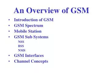
INTRODUCTION TO GSM INTRODUCTION • The Global System for Mobile Communications (GSM) is a set of recommendations and specifications for a digital cellular telephone network (known as a Public Land Mobile Network, or PLMN). • These recommendations ensure the compatibility of equipment from different GSM manufacturers, and interconnectivity between different administrations, including operation across international boundaries. • GSM networks are digital and can cater for high system capacities. • They are consistent with the world-wide digitization of the telephone network, and are an extension of the Integrated Services Digital Network (ISDN), using a digital radio interface between the cellular network and the mobile subscriber equipment.
INTRODUCTION TO GSM CELLULAR TELEPHONY • A cellular telephone system links mobile subscribers into the public telephone system or to another cellular subscriber. • Information between the mobile unit and the cellular network uses radio communication. Hence the subscriber is able to move around and become fully mobile. • The service area in which mobile communication is to be provided is divided into regions called cells. • Each cell has the equipment to transmit and receive calls from any subscriber located within the borders of its radio coverage area. Radio Cell Mobile subscriber
INTRODUCTION TO GSM GSM FREQUENCIES • GSM systems use radio frequencies between 890-915 MHz for receive and between 935-960 MHz for transmit. • RF carriers are spaced every 200 kHz, allowing a total of 124 carriers for use. • An RF carrier is a pair of radio frequencies, one used in each direction. • Transmit and receive frequencies are always separated by 45 MHz. UPLINK FREQUENCIES DOWNLINK FREQUENCIES 890 915 935 960 UPLINK AND DOWNLINK FREQUENCY SEPARATED BY 45MHZ
INTRODUCTION TO GSM Extended GSM (EGSM) • EGSM has 10MHz of bandwidth on both transmit and receive. • Receive bandwidth is from 880 MHz to 890 MHz. • Transmit bandwidth is from 925 MHz to 935 MHz. • Total RF carriers in EGSM is 50. UPLINK FREQUENCIES DOWNLINK FREQUENCIES 880 925 890 915 935 960 UPLINK AND DOWNLINK FREQUENCY SEPARATED BY 45MHZ
INTRODUCTION TO GSM DCS1800 FREQUENCIES • DCS1800 systems use radio frequencies between 1710-1785 MHz for receive and between 1805-1880 MHz for transmit. • RF carriers are spaced every 200 kHz, allowing a total of 373 carriers. • There is a 100 kHz guard band between 1710.0 MHz and 1710.1 MHz and between 1784.9 MHz and 1785.0 MHz for receive, and between 1805.0 MHz and 1805.1 MHz and between 1879.9 MHz and 1880.0 MHz for transmit. • Transmit and receive frequencies are always separated by 95 MHz. UPLINK FREQUENCIES DOWNLINK FREQUENCIES 1710 MHz 1785 MHz 1805 MHz 1880 MHz UPLINK AND DOWNLINK FREQUENCY SEPARATED BY 95MHZ
FEATURES OF GSM INCREASED CAPACITY • The GSM system provides a greater subscriber capacity than analogue systems. • GSM allows 25 kHz per user, that is, eight conversations per 200 kHz channel pair (a pair comprising one transmit channel and one receive channel). • Digital channel coding and the modulation used makes the signal resistant to interference from cells where the same frequencies are re-used (co-channel interference); a Carrier to Interference Ratio (C/I) level of 12 dB is achieved, as opposed to the 18 dB typical with analogue cellular. • This allows increased geographic reuse by permitting a reduction in the number of cells in the reuse pattern.
FEATURES OF GSM AUDIO QUALITY • Digital transmission of speech and high performance digital signal processors provide good quality speech transmission. • Since GSM is a digital technology, the signals passed over a digital air interface can be protected against errors by using better error detection and correction techniques. • In regions of interference or noise-limited operation the speech quality is noticeably better than analogue. USE OF STANDARDISED OPEN INTERFACES • Standard interfaces such as C7 and X25 are used throughout the system. Hence different manufacturers can be selected for different parts of the PLMN. • There is a high flexibilty in where the Network components are situated.
FEATURES OF GSM IMPROVED SECURITY AND CONFIDENTIALITY • GSM offers high speech and data confidentiality. • Subscriber authentication can be performed by the system to check if a subscriber is a valid subscriber or not. • The GSM system provides for high degree of confidentiality for the subscriber. Calls are encoded and ciphered when sent over air. • The mobile equipment can be identified independently from the mobile subscriber. The mobile has a identity number hard coded into it when it is manufactured. This number is stored in a standard database and whenever a call is made the equipment can be checked to see if it has been reported stolen.
FEATURES OF GSM CLEANER HANDOVERS • GSM uses Mobile assisted handover techique. • The mobile itself carries out the signal strength and quality measurement of its server and signal strength measurement of its neighbors. • This data is passed on the Network which then uses sophisticated algorithms to determine the need of handover. SUBSCRIBER IDENTIFICATION • In a GSM system the mobile station and the subscriber are identified separately. • The subscriber is identified by means of a smart card known as a SIM. • This enables the subscriber to use different mobile equipment while retaining the same subscriber number.
FEATURES OF GSM ENHANCED RANGE OF SERVICES • Speech services for normal telephony. • Short Message Service for point ot point transmission of text message. • Cell broadcast for transmission of text message from the cell to all MS in its coverage area. Message like traffic information or advertising can be transmitted. • Fax and data services are provided. Data rates available are 2.4 Kb/s, 4.8 Kb/s and 9.6 Kb/s. • Supplementary services like number identification , call barring, call forwarding, charging display etc can be provided.
FEATURES OF GSM FREQUENCY REUSE • There are total 124 carriers in GSM ( additional 50 carriers are available if EGSM band is used). • Each carrier has 8 timeslots and if 7 can be used for traffic then a maximum of 868 ( 124 X 7 ) calls can be made. This is not enough and hence frequencies have to be reused. • The same RF carrier can be used for many conversations in several different cells at the same time. • The radio carriers available are allocated according to a regular pattern which repeats over the whole coverage area. • The pattern to be used depends on traffic requirement and spectrum availability. • Some typical repeat patterns are 4/12, 7/21 etc. 2 1 3 4 5 7 6 2 1
NETWORK COMPONENTS H D F B C A UM ABIS UM
NETWORK COMPONENTS Mobile Switching Centre (MSC) • The Mobile services Switching Centre (MSC) co-ordinates the setting up of calls to and from GSM users. • It is the telephone switching office for MS originated or terminated traffic and provides the appropriate bearer services, teleservices and supplementary services. • It controls a number of Base Station Sites (BSSs) within a specified geographical coverage area and gives the radio subsystem access to the subscriber and equipment databases. • The MSC carries out several different functions depending on its position in the network. • When the MSC provides the interface between PSTN and the BSS in the GSM network it is called the Gateway MSC. • Some important functions carried out by MSC are Call processing including control of data/voice call setup, inter BSS & inter MSC handovers, control of mobility management, Operation & maintenance support including database management, traffic metering and man machine interface & managing the interface between GSM & PSTN N/W.
NETWORK COMPONENTS Mobile Switching Centre (MSC) – Lucent MSC
NETWORK COMPONENTS Mobile Station (MS) • The Mobile Station consists of the Mobile Equipment (ME) and the Subscriber Identity Module (SIM). Mobile Equipment • The Mobile Equipment is the hardware used by the subscriber to access the network. • The mobile equipment can be Vehicle mounted, with the antenna physically mounted on the outside of the vehicle or portable mobile unit, which can be handheld. • Mobiles are classified into five classes according to their power rating.
NETWORK COMPONENTS SIM • The SIM is a removable card that plugs into the ME. • It identifies the mobile subscriber and provides information about the service that the subscriber should receive. • The SIM contains several pieces of information • International Mobile Subscribers Identity ( IMSI ) - This number identifies the mobile subscriber. It is only transmitted over the air during initialising. • Temporary Mobile Subscriber Identity ( TMSI ) - This number also identifies the subscriber. It can be alternatively used by the system. It is periodically changed by the system to protect the subscriber from being identified by someone attempting to monitor the radio interface. • Location Area Identity ( LAI ) - Identifies the current location of the subscriber. • Subscribers Authentication Key ( Ki ) - This is used to authenticate the SIM card. • Mobile Station International Standard Data Number ( MSISDN ) - This is the telephone number of the mobile.
NETWORK COMPONENTS SIM • Mostof the data contained within the SIM is protected against reading (eg Ki ) or alterations after the SIM is issued. • Some of the parameters ( eg. LAI ) will be continously updated to reflect the current location of the subscriber. • The SIM card can be protected by use of Personal Identity Number ( PIN ) password. • The SIM is capable of storing additional information such as accumulated call charges. MINI SIM CARD FULL SIZE SIM CARD G S M
NETWORK COMPONENTS Mobile Station International Subscribers Dialling Number( MSISDN ) : • Human identity used to call a MS • The Mobile Subscriber ISDN (MSISDN) number is the telephone number of the MS. • This is the number a calling party dials to reach the subscriber. • It is used by the land network to route calls toward the MSC. CC NDC SN 98 XXX 12345 CC NDC SN = Country code = National Destination Code = Subscriber Number
NETWORK COMPONENTS International Mobile Subscribers Identity ( IMSI ) : • Network Identity Unique to a MS • The International Mobile Subscriber Identity (IMSI) is the primary identity of the subscriber within the mobile network and is permanently assigned to that subscriber. • The IMSI can be maximum of 15 digits. MNC MSIN MCC 404 XX 12345..10 MCC MNC MSIN = Mobile Country Code ( 3 Digits ) = Mobile Network Code ( 2 Digits ) = Mobile Subscriber Identity Number
NETWORK COMPONENTS Temporary Mobile Subscribers Identity ( TMSI ) : • The GSM system can also assign a Temporary Mobile Subscriber Identity (TMSI). • After the subscriber's IMSI has been initialized on the system, the TMSI can be used for sending messages backwards and forwards across the network to identify the subscriber. • The system automatically changes the TMSI at regular intervals, thus protecting the subscriber from being identified by someone attempting to monitor the radio channels. • The TMSI is a local number and is always allocated by the VLR. • The TMSI is maximum of 4 octets.
NETWORK COMPONENTS Equipment Identity Register ( EIR ) • The Equipment Identity Register (EIR) contains a centralized database for validating the international mobile station equipment identity, the IMEI. • The database contains three lists: • The white list contains the number series of equipment identities that have been allocated in the different participating countries. This list does not contain individual numbers but but a range of numbers by identifying the beginning and end of the series. • The grey list contains IMEIs of equipment to be monitored and observed for location and correct function. • The black list contains IMEIs of MSs which have been reported stolen or are to be denied service. • The EIR database is remotely accessed by the MSC’s in the Network and can also be accessed by an MSC in a different PLMN. .
NETWORK COMPONENTS Equipment Identity Register ( EIR ) EIR White List All Valid assigned ID’s Range 1 Range 2 Range n Black List Service denied MS IMEI 1 MS IMEI 2 MS IMEI n Grey List Service allowed but noted MS IMEI 1 MS IMEI 2 MS IMEI n
NETWORK COMPONENTS International Mobile Equipment Identity ( IMEI ) : • IMEI is a serial number unique to each mobile • Each MS is identified by an International Mobile station Equipment Identity (IMEI) number which is permanently stored in the Mobile Equipment. • On request, the MS sends this number over the signalling channel to the MSC. • The IMEI can be used to identify MSs that are reported stolen or operating incorrectly. TAC FAC SNR SP 6 2 6 1 TAC FAC SNR SP = Type Approval Code = Final Assembly Code = Serial Number = Spare
NETWORK COMPONENTS HOME LOCATION REGISTER( HLR ) • The HLR contains the master database of all subscribers in the PLMN. • This data is remotely accessed by the MSC´´s and VLRs in the network. The data can also be accessed by an MSC or a VLR in a different PLMN to allow inter-system and inter-country roaming. • A PLMN may contain more than one HLR, in which case each HLR contains a portion of the total subscriber database. There is only one database record per subscriber. • The subscribers data may be accessed by the IMSI or the MSISDN. • The parameters stored in HLR are • Subscribers ID (IMSI and MSISDN ) • Current subscriber VLR. • Supplementary services subscribed to. • Supplementary services information (eg. Current forwarding address ). • Authentication key and AUC functionality. • TMSI and MSRN
NETWORK COMPONENTS VISITOR LOCATION REGISTER ( VLR ) • The Visited Location Register (VLR) is a local subscriber database, holding details on those subscribers who enter the area of the network that it covers. • The details are held in the VLR until the subscriber moves into the area serviced by another VLR. • The data includes most of the information stored at the HLR, as well as more precise location and status information. • The additional data stored in VLR are • Mobile status ( Busy / Free / No answer etc. ) • Location Area Identity ( LAI ) • Temporary Mobile Subscribers Identity ( TMSI ) • Mobile Station Roaming Number ( MSRN ) • The VLR provides the system elements local to the subscriber, with basic information on that subscriber, thus removing the need to access the HLR every time subscriber information is required.
NETWORK COMPONENTS Authentication Centre ( AUC ) • The AUC is a processor system that perform authentication function. • It is normally co-located with the HLR. • The authentication process usually takes place each time the subscriber initialises on the system. • Each subscriber is assigned an authentication key (Ki) which is stored in the SIM and at the AUC. • A random number of 128 bits is generated by the AUC & sent to the MS. • The authentication algorithm A3 uses this random number and authentication key Ki to produce a signed response SRES( Signed Response ). • At the same time the AUC uses the random number and Authentication algoritm A3 along with the Ki key to produce a SRES. • If the SRES produced by AUC matches the one produced by MS is the same, the subscriber is permitted to use the network.
NETWORK COMPONENTS AUTHENTICATION PROCESS HLR AUC MS Ki, A3, A8 A3 ( RAND, Ki ) = SRES A8 ( RAND, Ki ) = Kc Triples Generated A3 , A8 , A5 , Ki RAND TRIPLES RAND, Kc , SRES VLR SRES = A3 (RAND , Ki ) SRES RAND Kc SRES SRES SRES = SRES BTS AIR INTERFACE ENCRYPTION A5 , HYPERFRAME NUM Kc = A8 (RAND , Ki ) Kc
NETWORK COMPONENTS Base Station Sub-System ( BSS ) : • The BSS is the fixed end of the radio interface that provides control and radio coverage functions for one or more cells and their associated MSs. • It is the interface between the MS and the MSC. • The BSS comprises one or more Base Transceiver Stations (BTSs), each containing the radio components that communicate with MSs in a given area, and a Base Site Controller (BSC) which supports call processing functions and the interfaces to the MSC. • Digital radio techniques are used for the radio communications link, known as the Air Interface, between the BSS and the MS. • The BSS consists of three basic Network Elements (NEs). • Transcoder (XCDR) or Remote transcoder (RXCDR) . • Base Station Controller (BSC). • Base Transceiver Stations (BTSs) assigned to the BSC. .
NETWORK COMPONENTS Transcoder( XCDR ) • The speech transcoder is the interface between the 64 kbit/s PCM channel in the land network and the 13 kbit/s vocoder (actually 22.8 kbit/s after channel coding) channel used on the Air Interface. • This reduces the amount of information carried on the Air Interface and hence, its bandwidth. • If the 64 kbits/s PCM is transmitted on the air interface without occupation, it would occupy an excessive amount of radio bandwidth. This would use the available radio spectrum inefficiently. • The required bandwidth is therefore reduced by processing the 64 kbits/s PCM data so that the amount of information required to transmit digitized voice falls to 13kb/s. • The XCDR can multiplex 4 traffic channels into a single 64 kbit/s timeslot. Thus a E1/T1 serial link can carry 4 times as many channels. • This can reduce the number of E1/T1 leased lines required to connect remotely located equipment. • When the transcoder is between the MSC and the BSC it is called a remote transcoder (RXCDR).
NETWORK COMPONENTS TRANSCODER(XCDR) - Siemens
NETWORK COMPONENTS TRANSCODING 30 Timeslots 1 traffic channel / TS 64 Kbps / TS 4 E1 lines = 30 X 4 =120 Timeslots Each Timeslot =16 X 4 = 64 Kb/s 30 timeslots = 30 x 4 =120 traffic channels MSC XCDR BSC Transcoded information from four calls 0 1 2 16 31
NETWORK COMPONENTS Base Station Controller (BSC) • The BSC network element provides the control for the BSS. • It controls and manages the associated BTSs, and interfaces with the Operations and Maintenance Centre (OMC). • The purpose of the BSC is to perform a variety of functions. The following comprise the functions provided by the BSC: • Controls the BTS components.- • Performs Call Processing. • Performs Operations and Maintenance (O & M). • Provides the O & M link (OML) between the BSS and the OMC. • Provides the A Interface between the BSS and the MSC. • Manages the radio channels. • Transfers signalling information to and from MSs.
NETWORK COMPONENTS Base Station Controller (BSC) – Siemens BSC
NETWORK COMPONENTS Base Transceiver Station (BTS) • The BTS network element consists of the hardware components, such as radios, interface modules and antenna systems that provide the Air Interface between the BSS and the MSs. • The BTS provides radio channels (RF carriers) for a specific RF coverage area. • The radio channel is the communication link between the MSs within an RF coverage area and the BSS. • The BTS also has a limited amount of control functionality which reduces the amount of traffic between the BTS and BSC.
NETWORK COMPONENTS Base Transceiver Station (BTS)
NETWORK COMPONENTS BTS Connectivity Open ended Daisy Chain MSC BSC BTS12 BTS13 BTS14 Star BTS5 BTS11 Daisy Chain with a fork. Fork has a return loop back to the chain BTS1 BTS6 BTS4 Daisy Chain with a fork. Fork has a return loop back to the chain BTS2 BTS7 BTS9 BTS8 BTS11 BTS3
NETWORK COMPONENTS Operation And Maintenance Centre For Radio (OMC-R) • The OMC controls and monitors the Network elements within a region. • The OMC also monitors the quality of service being provided by the Network. • The following are the main functions performed by the OMC-R • The OMC allows network devices to be manually removed for or restored to service. The status of network devices can be checked from the OMC and tests and diagnostics invoked. • The alarms generated by the Network elements are reported and logged at the OMC. The OMC-R Engineer can monitor and analyze these alarms and take appropriate action like informing the maintenance personal. • The OMC keeps on collecting and accumulating traffic statistics from the network elements for analysis. • Software loads can be downloaded to network elements or uploaded to the OMC.
NETWORK COMPONENTS Operation And Maintenance Centre For Radio (OMC-R)
NETWORK COMPONENTS Base Station Identity Code • BSIC allows a mobile station to distinguish between neighboring base stations. • It is made up of 8 bits. NCC = National Colour Code( Differs from operator to operator ) BCC = Base Station Colour Code, identifies the base station to help distinguish between Cell’s using the same BCCH frequencies 7 6 5 4 3 2 1 0 0 0 BCC NCC BCC
NETWORK COMPONENTS MS Class Mark • The MS is identified by it’s classmark which the mobile sends during it’s initial message. • The classmark contains the following information • Revision level - Identifies the phase of the GSM specifications the mobiles complies with. • RF Power Capabilities - The maximum power the mobile can transmit. This information is held in the MS Power Class Number. • Ciphering Algorithm - Indicates the ciphering algorithm implemented in the mobile. There is only one algorithm (A5 ) in GSM phase 1, however GSM phase 2 specifies different algorithms (A5/0 to A5/7 ) • Frequency Capability - Indicates the frequency bands the MS can receive and transmit on. • Short Message Capability- Indicates whether the MS is able to receive short messages or not.
MOBILE MAXIMUM RANGE RANGE= TIMING ADVANCE = DELAY OF BITS (0-63) BIT PERIOD= 577/156.25 = 3.693sec =3.693 * 10e-6 sec VELOCITY= 3 * 10e5 Km/sec RANGE= 34.9 Km TIMIMG ADVANCE * BIT PERIOD* VELOCITY 2
MULTIPLE ACCESS TECHNIQUES • Inorder for several links to be in progress simultaneously in the same geographical area without mutual interference , multiple access techniques are deployed. • The commonly used multiple access techniques are • Frequency Division Multiple Access (FDMA ) • Time Division Multiple Access (TDMA ) • Code Division Multiple Access (CDMA )
TERRESTERIAL INTERFACE • The terrestrial interfaces comprises all the connections between the GSM system entities ,apart from the Um or air interface. • The terrestrial interfaces transport the traffic across the systemand allows the passage of thousands of data messages to make the system function. • The standard interfaces used are • 2 Mb/s • Signalling System (C7 or SS7 • Packet Switched Data • A bis using the LAPD protocol (Link Access Procedure D )
INTERFACE NAMES Each interface specified in GSM has a name associated with it. NAMEINTERFACE Um MS ----- BTS Abis BTS ----- BSC A MSC ------ BSC B MSC ------ VLR C MSC ------ HLR D VLR ----- HLR E MSC ------ MSC F MSC ------ EIR G VLR ------ VLR H HLR ------ AUC