Download
1 / 42
660 likes | 1.63k Views
7. Programming Logic Gate Functions in PLCs. Objectives. Describe combinational and sequential logic gate circuits. Create PLC ladder logic programs for NOT, AND, OR, NAND, NOR, XOR, and XNOR logic gates. Create Boolean expressions and logic gate circuits from truth tables. Objectives.

E N D
7 Programming Logic Gate Functions in PLCs
Objectives • Describe combinational and sequential logic gate circuits. • Create PLC ladder logic programs for NOT, AND, OR, NAND, NOR, XOR, and XNOR logic gates. • Create Boolean expressions and logic gate circuits from truth tables.
Objectives • Use the Logic Converter instrument in NI Multisim to create logic tables and Boolean expressions from logic gate circuits. • Convert Boolean expressions to PLC ladder logic diagrams. • Convert PLC ladder logic diagrams to logic gate circuits and Boolean expressions.
Combinational Logic Gates • Do not require clock pulses to operate. • Outputs depend only on their inputs. • Outputs are generated instantaneously. • Simply called logic gates.
Logic Gates • NOT. • AND. • OR. • NAND. • NOR. • XOR (exclusive OR). • XNOR (exclusive NOR).
Sequential Logic Devices • Have outputs that depend on their inputs as well as time. • Require clock pulses. • An inherent delay time is always present. • Flip-flop devices.
Boolean Expressions • Every gate logic function has its own equation called a Boolean expression. • Boolean algebra: • Two states are true and false.
Boolean Expressions (Cont.) • True state: • Represented by the number one, called logic high or logic one in Boolean algebra. • False state: • Represented by the number zero, called logic low or logic zero.
Boolean Expressions (Cont.) • Logic high: • Represented by the presence of a voltage potential. • Represented with five volts (+5 V). • Logic low: • Represented by the absence of a voltage potential. • Represented with zero volts (0 V).
Truth Tables • In Boolean algebra, a table contains the digital input and output points. • This table is called a truth table.
Gate Symbols • For every combinational and sequential logic device. • Used to create logic gate circuits.
NOT Gate • Output is the inverse of the input. • Sometimes called an inverter. • Function is simulated by the electric circuit displayed.
AND Gate • Two-input AND logic gate symbol, its Boolean expression, and its truth table.
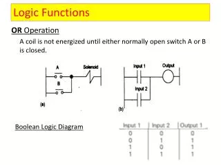
OR Gate • Two-input OR logic gate symbol, its Boolean expression, and its truth table.
NAND Gate • Two-input NAND logic gate symbol, Boolean expression, and its truth table.
NOR Gate • A two-input NOR logic gate symbol, its Boolean expression, and its truth table.
XOR (exclusive OR)Gate • XOR logic gate symbol, its Boolean expression, and its truth table.
XNOR logic gate symbol, its Boolean expression, and its truth table. XNOR (exclusive NOR) Gate
Simplifying Boolean Expressions • To convert a truth table to a PLC ladder logic diagram: • Find its simplified Boolean expression. • Use the gate logic to PLC ladder diagram conversion routine to create the PLC ladder logic diagram.
Simplifying Boolean Expressions (Cont.) • Three methods used to simplify Boolean expressions: • Karnaugh maps. • Quine-McCluskey routine. • Electronic simulation software.
Karnaugh Maps (K-Map) • Graphical representations of truth tables. • Use columns and rows to represent each term in a truth table. • For an n-variable input truth table, there are 2nboxes in a Karnaugh map. • A box for every line in the truth table.
Using K-Maps • Use the following steps to simplify the Boolean expressions using K-Maps: • Select an appropriate K-Map that has the correct number of input boxes, such as two-input and three-input. As stated, for an n-variable input truth table, there will be 2nboxes. Therefore, for a two-variable (A and B) input table, there will be 22 boxes, or 4 boxes. • Plot only the terms in which Y = 1.
Using K-Maps (Cont.) 3. Follow the rules below for grouping the 1s in the K-Map that lead to simplifying the expression.
Using K-Maps (Cont.) • Each group must contain an even number of binary 1s.
Using K-Maps (Cont.) • Every 1 in adjacent cells must be included in a group. • The same 1 can be used in two or more overlapping groups. Each group should be as large as possible.
Using K-Maps (Cont.) • Map can be considered closed, so that end boxes are grouped adjacently (top and bottom, or left and right).
Using K-Maps (Cont.) • How groups wrap around the K-Map.
Using K-Maps (Cont.) 4. Write the Boolean expressions for each group, and then simplify the expression.
Using K-Maps (Cont.) 5. Sum common variables from each group to create simplified sum of product (SOP) Boolean expression.
Quine-McCluskey Routine • For more than five input variables, a better method for simplifying Boolean expressions. • Complicated method that uses the Boolean algebraic simplification rules to find the simplified Boolean expression. • Might be used in an advanced course.
Electronic Simulation Software • Easiest method to find simplified Boolean expression: • Enter input and output data. • Solves and simplifies the expression. • NI Multisim is an example of this software.
NI Multisim Software • Open NI Multisim program. • From the Instruments toolbar, click the Logic Converter icon. • Click a space in the work area to place the converter. • Double-click the Logic Converter image to open the Logic Converter dialog box.
Creating PLC Ladder Logic Diagrams from Logic Gate Circuits • Convert each gate to its equivalent ladder logic diagram.
Creating PLC Ladder Logic Diagrams from Boolean Expressions • Some manufacturers use Boolean expressions to program PLCs. Example • Create the PLC ladder logic diagram for the following Boolean expression. Y = A′ + B + CD + EB
Creating PLC Ladder Logic Diagrams from Boolean Expressions (Cont.) • To create the diagram, each rung or each portion of a rung is created by replacing the Boolean letter with the inputs that match.
Creating Logic Gate Circuits from PLC Ladder Logic Diagrams • Converting to logic gate circuits: • Find Boolean expression that represents ladder logic diagram. • Draw the logic gate circuit using the Boolean expression similar. • Use logic converter instrument in NI Multisim program to find truth tables and Boolean expressions.
Creating Logic Gate Circuits from PLC Ladder Logic Diagrams (Cont.) • Create the logic gate circuit for the PLC ladder logic diagram displayed.
Creating Logic Gate Circuits from PLC Ladder Logic Diagrams (Cont.) • Turn the PLC ladder logic diagram into a Boolean expression as shown in the ladder diagram.