Download
1 / 37
370 likes | 371 Views
Learn about VHDL, a hardware description language used for modeling and designing digital systems. Explore its concepts, language standards, and application in hardware design.

E N D
Hardware Description Languages Basic Concepts مرتضي صاحب الزماني
Application of HDLs • VHDL به عنوان زبان مستندسازي (توصيف فرمال و بدون ابهام). • سنتز: تبديل (اتوماتيك يا دستي) يك توصيف به توصيفي با جزئيات بيشتر مرتضي صاحب الزماني
A digital system design process Synthesis Place & Route مرتضي صاحب الزماني
Simulation Synthesis Place & Route مرتضي صاحب الزماني
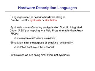
VHDL - Overview • Very High Speed Integrated Circuit Hardware Description Language • Modeling of digital systems • Concurrent and sequential statements • Design lifetime > Designer lifetime • Man- and machine-readable documentation • International Standards • IEEE Std 1076-1987 • IEEE Std 1076-1993, 2000, 2002, … مرتضي صاحب الزماني
VHDL - History • 2003: VHDL-200X by VASG (VHDL Analysis and Standardization Group) • Responsible for maintaining and extending the VHDL standard (IEEE 1076). • 2005: Accellera VHDL TSC took over. • 2006: Accellera VHDL-2006-D3.0 approved • DATE 2007: date_vhdl_tutorial.pdf • Pure definition of language in the LRM (Language Reference Manual) • No standards for application or methodology مرتضي صاحب الزماني
VHDL Standards • علاوه بر استانداردهاي خالص, تلاشهايي براي استاندارد كردن عوامل مربوط به VHDL انجام گرفته است: • پكيج هاي • Std_logic_1164 • Numeric_bit • Numeric_std • زيرمجموعة قابل سنتز: استاندارد1076.6 • VHDL-AMS 1076.1 مرتضي صاحب الزماني
VHDL - Overview • در حال حاضر براي VHDL-AMS فقط شبيه سازي امكان پذير است چون سنتز آنالوگ بسيار پيچيده است. • شبيه سازي Mixed Signal هم مسايل همگام سازي شبيه سازهاي ديجيتال و آنالوگ و الگوريتمهاي حل معادلات ديفرانسيل غيرخطي را دارد. مرتضي صاحب الزماني
VHDL-Application Field • Hardware design • ASIC: technology mapping • توصيف به gate-level netlist تبديل مي شود و اجزا از كتابخانة ASIC انتخاب مي شوند. • FPGA, CPLD: LUT/PAL mapping • SPLD: smaller structures, hardly any use of VHDL مرتضي صاحب الزماني
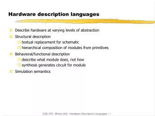
Concepts of VHDL • Execution of Statements: • Sequential • Concurrent • Methodologies: • Abstraction • Modularity • Hierarchy مرتضي صاحب الزماني
Concepts of VHDL • Abstraction: طرح را مي توان در سطوح مختلفي از جزئيات توصيف كرد: • براي مدلسازي، سطوح بالا كافي است. • براي سنتز، ممكن است جزئيات بيشتري لازم باشد. مرتضي صاحب الزماني
Concepts of VHDL • Modularity: مي توان بلوك بزرگ پيچيده را به بلوكهاي كوچكتر تقسيم كرد و براي هر بخش يك مدل نوشت. • Hierarchy: تشكيل يك درخت سلسله مراتبي • هر كدام از نودها ممكن است در سطح متفاوتي از abstraction توصيف شده باشد. مرتضي صاحب الزماني
Abstraction Levels in IC Design • VHDL براي سطح layoutمناسب نيست. مرتضي صاحب الزماني
Behavioral Description in VHDL • در VHDL رفتار عملياتي با process مدل مي شود. مرتضي صاحب الزماني
collect : PROCESS BEGIN WAIT UNTIL serial = '0'; WAIT FOR half_bit; FOR count IN 0 TO 7 LOOP WAIT FOR full_bit; buff (count) := serial; END LOOP; WAIT FOR full_bit; IF serial = '0' THEN frame_error <= '1'; WAIT UNTIL serial = '1'; ELSE frame_error <= '0'; dataready <= '1'; parallel_out <= buff; WAIT UNTIL received = '1'; WAIT UNTIL received = '0'; dataready <= '0'; END IF; END PROCESS collect; Behavioral Description constanthalf_bit:time:=50ns; constantfull_bit:time:=100ns; مرتضي صاحب الزماني
Dataflow (RTL) Description مرتضي صاحب الزماني
Dataflow (RTL) Description architecture RTL of MOORE_TEST is signal STATE,NEXTSTATE : STATE_TYPE ;begin REG: process (CLK, RESET) begin if RESET='1' then STATE <= START ; elsif CLK'event and CLK='1' then STATE <= NEXTSTATE ; end if ; end process REG ; OUTPUT_REG: process(CLK)beginif CLK'event and CLK='1' then Y <= S1 + S2; Z <= Z_I ;end if ;end process OUTPUT_REG ;end RTL ; مرتضي صاحب الزماني
Abstraction Levels and VHDL مرتضي صاحب الزماني
Structural Description • اجزا ممكن است گيت پيچيده باشند. مرتضي صاحب الزماني
Post-layout simulation ASIC Development CMOS 45 nm • بعد از شبيه سازي post-synthesis مي توان ماكزيمم فركانس كلاك را تخمين زد (بر اساس مسير بحراني موجود) • بعد از شبيه سازي post-layout مي توان ماكزيمم فركانس كلاك را به دست آورد مرتضي صاحب الزماني
Information Content in Abstraction Levels مرتضي صاحب الزماني
Modularity and Hierarchy • Partitioning in several partial designs • Restrict complexity • Enable teamwork • Study of alternative implementations • گاهي اوقات simulation model هايي از اجزا يا تراشه هاي استاندارد وجود دارند كه مي توان به طرح خود متصل كرد و نتايج شبيه سازي را در محيط واقعي مشاهده كرد. مرتضي صاحب الزماني
Design Tools Simulation
Tool Set • Synthesis • Place & Route • Simulation Tools • Timing Analysis • Power Analysis • Verification
Simulation Tools • Simulation Tools • Oblivious simulation • Event-driven logic simulation • Mixed-language simulation • Cycle-based simulation • Post-layout simulation
Simulation Tools • Types of Logic Simulators: • Oblivious: • Simple but inefficient • Event driven: • See the world as a series of discrete events • Cycle-based • Rough simulation for synchronous sequential designs
Oblivious Simualtor • Starts by a table and initial values • Evaluates periodically (even when no change in inputs) • Repeats until nothing is changed in a pass.
Event-Driven Simulator • Simulates when an event (change) at input(s) of a component • Only part of the design is evaluated
Event-Driven Simulator • When a gate input changes, it places a transaction (value, delay) on the driver of the delayed signal (e.g. gate output) • It will expire after delay • Changes its value • Repeats for other gates with changed inputs • Concurrency is handled. • Mostly used in industry
CB CB CB Cycle-based Simulation • RTL: • At the beginning of each cycle, propagate values from primary inputs and from register outputs into combinational blocks (CBs). • Compute the stable outputs of CBs, and store them in register inputs (they’ll move to outputs in the next cycle). RTL model مرتضي صاحب الزماني
Assume ‘zero-delay’ (don’t care about the transient delays) 1 Steady state Steady state Steady state 0 t Cycle 1 Cycle 2 Cycle 3 Zero-delay cycle-based simulation • Functionality and timing can be verified separately • Assumption: • Within each cycle, all signal changes occur in zero-delay • Only evaluate on the clock edge • First: evaluate all combinational logic • Next: latch values into state registers • Repeat on next clock edge مرتضي صاحب الزماني
Levelizing the gates • Within each Combinational Block, gates can be levelized(sorted in topological order) for evaluation. • Going by level number, every gate will be evaluated after its inputs have been computed. • So: we order the gates by the flow of data, and we don’t care about the real delays assume “0 delay”. • Combinational Feedbacks? A levelized CB مرتضي صاحب الزماني
Event vs. Cycle-Based Simulation مرتضي صاحب الزماني
Cycle-Based vs. Event-Driven • Event-driven: • Each internal node • Need scheduling and functions may be evaluated multiple times • Cycle-based: • Only boundary nodes • No delay information • Cycle-based does not detect glitches and setup/hold time violations, while event-driven does مرتضي صاحب الزماني
1x .001x 10x Simulation: Performance vs. Abstraction Cycle-based Simulator Event-driven Simulator Abstraction SPICE مرتضي صاحب الزماني Performance and Capacity
FF FF FF Z Why is it faster? • Node a has 5 transitions and b has 3 transitions. • Event-driven simulator reevaluates when inputs change • Gate A simulates 5 times, • Gate B: 9 times, • Gate C: 6 times • Total 20 times. • But for only these 3 gates b d a A B c C • Conclusion: • Event-driven is faster if few transitions (typically less than 5% active nodes). • In practice, experiments confirm that a cycle-based simulator is almost always 5-10 times faster (and uses less memory) • Cycle-based simulator simulates the entire circuit only once (at the end of current cycle) • All Gates in the circuit are simulated regardless whether their inputs have been changed. مرتضي صاحب الزماني