Download
1 / 30
310 likes | 542 Views
EDMS № 1312687. Mechanical design and tests of the new X-band flange. A. Samochkine. Contents. Aim and Testing Requirements Features in 3D model Drawings Tolerances Configurations Pre-series production Mechanical test results and comparison with simulations

E N D
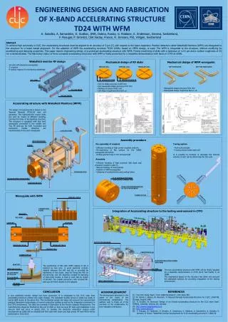
EDMS №1312687 Mechanical design and tests of the new X-band flange A. Samochkine
Contents Aim and Testing Requirements Features in 3D model Drawings Tolerances Configurations Pre-series production Mechanical test results and comparison with simulations Mechanical test results Proposal on configuration Knife “Squared shape" Gasket 1 mm thick Ref. : CLIAVACU0189 ST0436757
International Universal X-Band Flange (IUWR90) Mechanical design aim Develop WR90 common RF vacuum flange design in collaboration with different laboratories. PM Testing Tests on gaskets Assembly and disassembly; Leak tightness tests; Mechanical measurements; Baking.
Set of required flange features (Recommendation of committee. KEK collaboration meeting - May 2012) 1. Rectangular flange with 8 bolts 2. Precision outside dimensions for easy assembly verification 3. Grooves from gasket to outside of flange for leak test 4. Corners of gasket seat to be made circular for ease of gasket removal 5. No guide pins, study external alignment jig 6. Internal radius on corners of flange gasket knife to be made a big as reasonably possible 7. Simple rectangular copper gasket 1mm thick, completely annealed 8. Threaded hole on flange side for mounting 9. Minimize length of the RF part of flange (in case if used without copper plating). 10. Consider brazed side with round pockets near waveguide edges (like in KEK flange or Haimson's WR62).
Features in 3D model 1. Rectangular flange with 8 bolts 2. Precision outside dimensions for easy assembly verification 3. Grooves from gasket to outside of flange for leak test 4. Corners of gasket seat to be made circular for ease of gasket removal 5. No guide pins, study external alignment jig 6. Internal radius on corners of flange gasket knife to be made a big as reasonably possible 7. Simple rectangular copper gasket 1mm thick, completely annealed 8. Threaded hole on flange side for mounting 9. Minimize length of the RF part of flange (in case if used without copper plating). 10. Consider brazed side with round pockets near waveguide edges (like in KEK flange or Haimson's WR62). 2, 5 1 3 4 6 9 8 10 7
Design iterations • 2 main knife parameters: • 1. Flat knife edge width • 0.5 mm • 0.75 mm • 1 mm • 2. Gasket compression • 0.2 mm • 0.3 mm • 0.4 mm • 0.5 mm 12 versions
Flange drawing (CLIAVACU0189) Reference External surfaces
Copper coating Requirement 9 Machining dimensions before copper coating
Gasket drawings (CLIAVACU0190 & …191) +0.03 +0.01 +0.03 +0.01 -0.02 -0.04 -0.02 -0.04 20 32.7 CLIAVACU0190, clearance fit CLIAVACU0191, Interference fit
Procurement • Pre-series - procurement of 48 flanges • (12 configurations x 2 sets of 2 flanges each); - 50 gaskets with a clearance fit and 50 with interference fit • First seriesof 150 sets of the most successful configuration chosen through the pre-series phase.
Testing • Test on gasket compression (EDMS 1289259) • Dimensional control of gaskets after use (EDMS 1303470) • Thermal test of copper coating quality • 920 °C • 250 °C (according to ASTM B571-97) • Test on multiple usage of flange • Leak test (EDMS 1290515) • High power test at SLAC
Conclusions after gasket compression test • Two gaskets were inspected after use in assemblies of IUWR90 flanges. • The expansion of gasket into waveguide zone observed in case of flanges “4 – 4 1EM” is about 0.15 mm all around. • The expansion of gasket into waveguide zone observed in case of flanges “9 – 9 1EM” is about 0.1 mm all around. • The vacuum sealing is equally successful in both cases. • The use of flanges “9 – 9 1EM” is preferable because of smaller expansion into RF zone.
Gasket deformations after use (EDMS 1303470) [part2] • 10 different flange pairs of different designs (variation of “pressure width” “a” and “pressure depth” “b) • Every gasket has same initial dimensions • Assemblies are screwed together until stainless steel parts are in contact • After 48 hours, assemblies are dismounted and the deformed gaskets openings were measured. The aim is to assess how deep the gasket penetrates into RF volume after mounting as a function of “a” and “b” Openings measured in two ways: Ceramic gauge block set Optical Stereo microscope Flange New gasket Tested gasket new gaskets X₁ as initial verification X as final opening X₀ as reference opening tested gaskets and flanges -> accuracy depends on user: ~0.02 mm suitable and fast way of assessing the opening Measurements by M. Rissanen
Conclusions after dimensional control of used gaskets • The expansion of gasket into waveguide into the RF volume for design 12 • (highest “a” and smallest “b“) is biggest 0.295 mm • The expansion of gasket into waveguide into the RF volume for design 7 • (smallest “a” and biggest “b“) is smallest 0.079mm • For further reduction of the protrusion length “a” should be further decreased below 0.5 and “b” should be further increased above 0.4. The limit is represented only by the leak tightness, which is yet to be assessed.
Thermal test of copper coating quality 250 °C 920 °C • The copper plating on three flanges CLICAVACU0027 where tested according to the ATMS procedure “B571-97 TEST D’ADHESION INOX CUIVRE” chapter 9, Heat-Quench Test. • The procedure or testing the adhesion of copper coating to stainless steel: • heat up the copper coated stainless steel part to 250 °C and keep for 10 minutes (for being sure the whole part has uniform temperature) • rapid cooling in demineralised water at room temperature (20 °C). • If the copper plating doesn’t crack or start to peel of the coating is good. • Equipment: • The furnace used was a VENTICELL 222 with air filter class S DIN 24 184 and a forced ventilation. Brazing cycle was used to see if the copper coated flange sustains the heating (baking). The good copper adhesion is proved by both tests.
Test on multiple usage of fully copper coated flange The goal for these tests is to learn how the copper coating of the knife zone of the RF vacuum flange is affected during several assemblies with gaskets. The flange used was CLIAVACU0189 version 1, 6 and 12 The gaskets used were CLIAVACU0191 and CLIAVACU0190. First all combinations where assembled and studied. The combination with the biggest deformation on the gasket was chosen for the tests to be repeated. The greater the deformation of the gasket is, the bigger the impact on the knife was expected. After repeated assemblies more and more scratches appear. Small additional scratches appear after each assembly. The deformation of the gasket is also the biggest in shown zone. Assembled 4 times Assembled 9 times Inspection by F. Smeds
Conclusions after several assemblies • The whole flange copper coating is more cost effective. • The micro scratches observed on the knife surface after ten assemblies are negligible. That must be confirmed by deeper analysis (measurements).Most probably the annealed gasket will fill the cracks and scratches created during previous assembly. • Proposal for next steps • Vacuum leak tightness tests with plated flanges and repeated assemblies. • SEM pictures for deeper knowledge on the coating and the scratches.
Simulation of the gasket compression • The aim: • Evaluate the deformations of the gasket compressed between two flanges • Evaluate the torque required to tighten the screws • 12 gasket versions with varying flange knife dimensions FLANGE GASKET
Simulation of the gasket compression Gasket deformation under compression Study by L. Kortelainen
Sub-assemblies for high power test at SLAC CLIATLRF0128 CLIATLRF0129 Inlet inspection of 8 units of IUX Test setup assembly. (EDMS 1289257)
Leak test (EDMS # 1290515) • Leak detector type: ASM 121 h • Reference leak rate: 6.2±15% ×10⁻⁷mbar•l/s Minimum detectable leak rate: 2×10⁻¹⁰ mbar•l/s • Tracer gas: Helium 99% • System pressure: 1×10⁻³ mbar • Test temperature: 20 ̊C • Max. measured leak rate: Version 12/12 1EM & 1/1 1EM: 4.0 x 10⁻¹⁰ mbar•l/s Version 4/4 1EM & 9/9 1EM: 7.0 x 10⁻¹⁰ mbar•l/s
Shipping to SLAC for high power test 24-May-2013
Conclusions • From PM fabrication, inspection and tests: • Fully coated flange is recommended • Version 7 is recommended as it gives the smallest deformation • Waiting for High Power test results at SLAC to launch the series production
Alignment & fixation for example Clamping tool. Schematic view. Specially sized cantilever clamp with cylindrical grips to be designed. The self-adjustment in both, horizontal and vertical directions, as well as fixation before and during the bolts tightening is provided by pushing against the V-shaped grooves.
Two configurations Option 1 Option 2 Knife “Squared shape" Gasket 1 mm thick Knife “Improved" & optimized Gasket 2 mm thick
Gasket retention Minor friction keeps the gasket in place in any angular position