Download
1 / 30
300 likes | 417 Views
J. Osborne. LHeC Linac-Ring Option. Frank Zimmermann EucARD-AccNet-RFTech Workshop PSI, 2 December 2010. Linac-Ring LHeC – two options. 60-GeV recirculating linac with energy recovery. straight linac. performance targets. e- energy ≥60 GeV luminosity ~10 33 cm -2 s -1

E N D
J. Osborne LHeC Linac-Ring Option Frank Zimmermann EucARD-AccNet-RFTech Workshop PSI, 2 December 2010
Linac-Ring LHeC – two options 60-GeV recirculating linac with energy recovery straight linac
performance targets e- energy ≥60 GeV luminosity ~1033 cm-2s-1 total electrical power for e-: ≤100 MW e+p collisions with similar luminosity simultaneous with LHC pp physics e-/e+ polarization detector acceptance down to 1o getting all this at the same time is very challenging
road map to 1033 cm-2s-1 luminosity of LR collider: (round beams) average e- current ! highest proton beam brightness “permitted” (ultimate LHC values) ge=3.75 mm Nb=1.7x10¹¹ bunch spacing 25 or 50 ns • maximize geometric • overlap factor • head-on collision • small e- emittance • qc=0 • Hhg≥0.9 • smallest conceivable • proton b* function: • reduced l* (23 m → 10 m) • squeeze only one p beam • new magnet technology Nb3Sn • b*=0.1 m
electron beam e- emittances and b* not critical(protons are big, ~7mm!) most important parameter: average beam current in addition: bunch structureand polarization
target luminosity we need about 6 mA CLIC main beam ~ 0.01 mA (factor 600 missing) lowering voltage, raise bunch charge & rep rate → 0.06 mA (NIMA 2007) CLIC drive beam (30 mA, but 2.37 GeV) ILC design current ~ 0.05 mA (factor ~100 missing)
SC linacs can provide higher average current, e.g. by increasing the duty factor 10-100 times, or even running cw, at lower energy & lower gradient example design average currents:CERN HP-SPL: ~2.5 mA (50 Hz)Cornell ERL ~100 mA (cw)eRHIC ERL ~ 50 mA at 20 GeV (cw) LHeC needs ~6 mA at 60 GeV
beam power 6.4 mA at 60 GeV → 384 MW beam power ! → ~800 MW electrical power !!?? need for energy recovery! power reduced by factor (1-hERL) →LHeC ERL high-luminosity baseline
one more ingredient • choice of SC linac RF frequency: • 1.3 GHz (ILC)? • ~720 MHz?! • requires less cryo-power (~2 times less from BCS • theory); true difference ↔ residual resistance, • [J. Tückmantel, E. Ciapala] • better for high-power couplers? [O. Napoly] • but the couplers might not be critical • fewer cells better for trapped modes [J. Tückmantel] • synergy with SPL, eRHIC and ESS
ERL electrical site power cryo power for two 10-GeV SC linacs: 28.9 MW MV/m cavity gradient, 37 W/m heat at 1.8 K 700 “W per W” cryo efficiency RF power to control microphonics: 22.2 MW 10 kW/m (eRHIC), 50% RF efficiency RF for SR energy loss compensation: 24.1 MW energy loss from SR 13.2 MW, 50% RF efficiency cryo power for compensating RF: 2.1 MW 1.44 GeV linacs microphonics control for compensating RF: 1.6 MW injector RF: 6.4 MW 500 MeV, 6.4 mA, 50% RF efficiency magnets: 3 MW RFTech guidance requested! grand total = 88.3 MW
The eRHIC-type cryo-module containing six 5-cell SRF 703 MHz cavities. I. Ben-Zvi Model of a new 5-cell HOM-damped SRF 703 MHz cavity.
measured Q vs. field for the 5-cell 704 MHz cavity built and tested (BNL -I) I. Ben-Zvi
predicted cryopower based on eRHIC I. Ben-Zvi The relevant parameters for BNL-I cavity and for new 5-cell cavity upon which we based our calculations (BNL-III) are:Parameter Units Value BNL-I Value BNL-IIIGeometry factor Ohms 225 283R/Q per cell Ohms 80.8 101.3Bpeak/Eacc mT/MV/m 5.78 4.26Calculation:Assume Q vs. E as measured for BNL-I. Assume 18 MV/m operation. Assume losses scale with surface magnetic field.For comparison with measured results, scale field by the magnetic field ratio of BNL-III to BNL-I, giving 13.3 MV/m.The measured Q for BNL-I at this field is 4E10.Assume losses scale down by the geometry factor, that leads to a Q of 5E10.With this Q at 18 MV/m the cryogenic load is 13 W/cavity at 1.8 K (instead of 37 W/cavity!)
LHeC ERL RF system at 721 MHz E. Ciapala, LHeC 2010 Energy = 3 * 20 GeV, 2 x 10 GeV Linacs, 6.6 mA, Take 721 MHz, to allow 25 ns bunches • Take SPL type cavity @18 MV/m (similar to BNL design for eRHIC) • 1.06 m/cavity => 19.1 MV/cav => 1056 cavities total (=132 x 8) • Take 8 cavities in a 14 m cryomodule (cf SPL) => 66 cryomodules/linac • Total length = 924 m/linac + margin ~10% • Power loss in arcs = 14.35 MW, 13.6 kW/cavity, Take Prf = 20 kW/cavity with overhead for feedbacks, total installed RF 21 MW. • No challenge for power couplers, power sources – could be solid state • However, still need adjacent gallery to house RF equipment (high gradient = radiation !) 4-5 m diameter sufficient • Synchrotron radiation losses in arcs: Energy difference accelerated and decelerated beam • Can it be fully compensated by adjusting phases in the linacs, or do we need re-accelerating ‘mini’-linacs? – Needs further study • Question Could hardware prototyping be initiated, on SC cavities, - good synergy with SPL Proton driver study which is well underway, test of ERL concept at CERN ?
ERL configuration tune-up dump comp. RF 10-GeV linac injector 0.12 km 0.17 km comp. RF 20, 40, 60 GeV 1.0 km 2.0 km 10, 30, 50 GeV LHC p dump 10-GeV linac IP 0.26 km 0.03 km e- final focus total circumference ~ 8.9 km
ERL component lengths 10-GeV linac length: 1008 m cavity length 1 m, 56 m long FODO cell with 32 cavities, #cavities/linac = 576, cavity filling factor = 57.1% effective arc radius = 1000 m bending radius = 764 m, dipole filling factor = 76.4% (A. Bogacz) SRF compensation linac: maximum 84 m [at 60 GeV] combiners & splitters: 20-30 m each e- final focus: 200-230 m (R. Tomas) total circumference = LHC circumference / 3 (D. Schulte)
underground layout / integration with LHC LHeC area J.Osborne / A.Kosmicki CERN/GS
underground layout / integration with LHC J.Osborne / A.Kosmicki CERN/GS
underground layout / integration with LHC SHAFT #1 SHAFT #2 SHAFT #4 ALICE SHAFT #3 PMI2 LHC TI2 J.Osborne / A.Kosmicki CERN/GS
underground layout / integration with LHC TI2 LHC SHAFT #3 SHAFT #4 • use of existing TI2 tunnel • separate klystron gallery UJ22 J.Osborne / A.Kosmicki CERN/GS
beam-beam effects • protons • head-on tune shift: DQ=0.0001 tiny • long-range effect: none • 36 sp separation at s=3.75 m • emittance growth due to e-beam position jitter • pkick 10 nrad (~10-4s*’) for 1s offset, • e- turn-to-turn random orbit jitter ≤ 0.04s • [scaled from K. Ohmi, PAC’07; • see also D. Schulte, F. Zimmermann, EPAC2004] • electrons • disruption • Dx,y≈6, q0≈600 mrad (≈10s*’) large can we achieve this stability?
e & optics change during collision Bmagx,y ex,y ~180% potential growth from mismatch ~15% growth in emittance ax,y bx,y emittance after collision is at the most 3x initial emittance; emittance growth can be reduced to 15% by rematching extraction optics to b*~3 cm
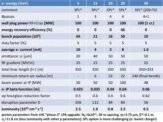
pulsed linac for 140 GeV 7.9 km IP 140-GeV linac dump injector 0.4 km final focus • linac could be ILC type (1.3 GHz) or 720 MHz • cavity gradient: 31.5 MV/m, Q=1010 • extendable to higher beam energies • no energy recovery • with 10 Hz, 5 ms pulse, Hg=0.94, Nb=1.5x10⁹ : <Ie>=0.27 mA → L≈4x1031 cm-2s-1
highest-energy LHeC ERL option high energy e- beam is not bent; could be converted into LC? High luminosity LHeC with nearly 100% energy efficient ERL. The main high-energy e- beam propagates from left to right. In the 1st linac it gains ~150 GeV (N=15), collides with the hadron beam and is then decelerated in the second linac. Such ERL could push LHeC luminosity to 1035 cm-2s-1 level. V. Litvinenko, 2nd LHeC workshop Divonne 2009 this looks a lot like CLIC 2-beam technology
summary ERL (60 GeV): 1033 cm-2s-1 , <100 MW, < 9 km circumference, about 21 GV RF pulsed linac (140 GeV) 4x1031 cm-2s-1 , <100 MW, < 9 km length, with g-p option high polarization possible, beam-beam benign, e+ difficult
questions to RFTech experts LHeC ERL: 721 MHz or 1.3 GHz? Cryo power (heat load at 1.8 K in cw)? Power to control microphonics? Linac position jitter?
contributors S. Bettoni, C. Bracco, O. Brüning, H. Burkhardt, E. Ciapala, B. Goddard, F. Haug, B. Holzer, B. Jeanneret, M. Jimenez, J. Jowett, A. Kosmicki, K.-H. Mess, J. Osborne, L. Rinolfi, S. Russenschuck, D. Schulte, H. ten Kate, H. Thiesen, R. Tomas, D. Tommasini, F. Zimmermann, CERN, Switzerland; C. Adolphsen, M. Sullivan, Y.-P. Sun, SLAC, USA; A.K. Ciftci, R. Ciftci, K. Zengin, Ankara U.,Turkey; H. Aksakal, E. Arikan, Nigde U., Turkey; E. Eroglu, I. Tapan, Uludag U., Turkey; T. Omori, J. Urakawa, KEK, Japan ; S. Sultansoy, TOBB, Turkey; J. Dainton, M. Klein, Liverpool U., UK; R. Appleby, S. Chattopadhyay, M. Korostelev, Cockcroft Inst., UK; A. Polini, INFN Bologna, Italy; E. Paoloni, INFN Pisa, Italy; P. Kostka, U. Schneekloth, DESY, Germany; R. Calaga, Y. Hao, D. Kayran, V. Litvinenko, V. Ptitsyn, D. Trbojevic, N. Tsoupas, V. Yakimenko, BNL, USA; A. Eide, NTNU, Norway ; A. Bogacz, JLAB, USA ; N. Bernard, UCLA, USA et al