Download

1 / 31
310 likes | 436 Views
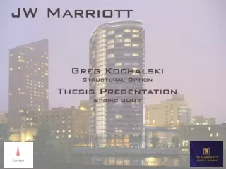
Structural System Redesign. Existing Conditions Proposal Gravity Design Lateral Design Cost Comparison Schedule Impact Conclusions. Existing Conditions Proposal Gravity Design Lateral Design Cost Comparison Schedule Impact Conclusions. Existing Conditions. Location: New York, NY

E N D
Structural System Redesign Existing Conditions Proposal Gravity Design Lateral Design Cost Comparison Schedule Impact Conclusions
Existing Conditions Proposal Gravity Design Lateral Design Cost Comparison Schedule Impact Conclusions Existing Conditions Location: New York, NY Owner: NYC HHC Architect:RMJM Hillier Structural Engineer: Greenman-Pedersen Inc. Construction: September 2008 – Mid 2012 Cost: $160 million overall project cost Delivery: Design-Bid-Build with multiple prime contracts
Existing Conditions Existing Conditions Proposal Gravity Design Lateral Design Cost Comparison Schedule Impact Conclusions • 75,000 sq. ft. Addition to Existing Hospital • 13 Stories • Steel Framed Addition • Concrete Existing Structure • 11’ Floor-to-Floor
Existing Conditions Existing Conditions Proposal Gravity Design Lateral Design Cost Comparison Schedule Impact Conclusions 3rd Floor Framing Plan 8th Floor Framing Plan • Cellular Beams for all Gravity Members • Moment Frames • Braced Frames
Existing Conditions Existing Conditions Proposal Gravity Design Lateral Design Cost Comparison Schedule Impact Conclusions Design Choices Use of Steel Framing Removal of Column Line Use of Moment Frames Impact Need Cellular Beams Heavy Lateral Members Further Restrictions on MEP systems
Proposal Existing Conditions Proposal Gravity Design Lateral Design Cost Comparison Schedule Impact Conclusions Proposal - Redesign current, steel-framed addition as a concrete structure utilizing two-way flat plate slab and shearwalls Design Goals - Maintain regularity in design Slab Column Shearwalls Provide design freedom for other systems Design a more cost effective structural system
Proposal Existing Conditions Proposal Gravity Design Lateral Design Cost Comparison Schedule Impact Conclusions Codes ASCE7-05 Wind Loads as per Chapter 6 Seismic Loads using Equivalent Later Force ACI 318-08 Methodology ETABS RAM Concept PCA Column Microsoft Excel
3rd Floor Plan Structure Overview Existing Conditions Proposal Gravity Design Lateral Design Cost Comparison Schedule Impact Conclusions Gravity System 12” slab fc’ = 6ksi 22’ x 24’ bay 16” columns 20” columns Lateral System 6 shearwalls 16” shearwalls 20” shearwalls
Gravity Design Existing Conditions Proposal Gravity Design Lateral Design Cost Comparison Schedule Impact Conclusions Design Loads - 26 psf Superimposed Dead Load - 80 psf Live Load Deflection Limits - L/360 Immediate Live Load Defl. - L/480 Long-term Deflection - L/240 Long-term Deflection Creep Factor = 2 20% of Live Load
3rd Floor Reinforcing Plan Slab Design Existing Conditions Proposal Gravity Design Lateral Design Cost Comparison Schedule Impact Conclusions Bottom Reinforcing
3rd Floor Reinforcing Plan Slab Design Existing Conditions Proposal Gravity Design Lateral Design Cost Comparison Schedule Impact Conclusions Top Reinforcing
3rd Floor Deflection Plan Initial. LL Deflection: 0.0555 in Slab Design Existing Conditions Proposal Gravity Design Lateral Design Cost Comparison Schedule Impact Conclusions Allowable: L/360 = 0.80 in Max. long-term Deflection: 0.4438 in Allowable: L/480 = 0.60 in
Typical Column Details Column Design Existing Conditions Proposal Gravity Design Lateral Design Cost Comparison Schedule Impact Conclusions Columns supporting 6 stories: 16” x 16” fc’= 6 ksi Columns supporting 13 stories: 20” x 20” fc’= 6 ksi
Slender Column Design Column Design Existing Conditions Proposal Gravity Design Lateral Design Cost Comparison Schedule Impact Conclusions
Column Design Existing Conditions Proposal Gravity Design Lateral Design Cost Comparison Schedule Impact Conclusions Column G/5.8 (6 stories): 16” x 16” fc’= 6 ksi Column F/5.8 (13 stories): 22” x 22” fc’= 6 ksi Slender Column Design
9th Floor Plan Transfer Beam Design Existing Conditions Proposal Gravity Design Lateral Design Cost Comparison Schedule Impact Conclusions Column Shift Control Deflections Match Floorplan Layout
Transfer Beam Design Existing Conditions Proposal Gravity Design Lateral Design Cost Comparison Schedule Impact Conclusions Column Shift Control Deflections Match Floorplan Layout 60” deep beam 20” width
Transfer Beam Design Existing Conditions Proposal Gravity Design Lateral Design Cost Comparison Schedule Impact Conclusions 60” deep beam 20” width
Lateral Design Existing Conditions Proposal Gravity Design Lateral Design Cost Comparison Schedule Impact Conclusions Design Assumptions ETABS Diaphragms modeled as Rigid and Semi-Rigid Shearwalls modeled as Membranes 0.7 f22 modifier for shearwalls 0.35 I3 modifier for coupling beam Deflection:H/400 for wind 0.015hx for seismic 3.00” overall floor deflection 3.50” overall deflection at roof 12.12.3 Building Separation. All portions of the structure shall be designed and constructed to act as an integral unit in resisting seismic forces unless separated structurally by a distance sufficient to avoid damaging contact under total deflection (δx) as determined in Section 12.8.6
Lateral Design - Seismic Existing Conditions Proposal Gravity Design Lateral Design Cost Comparison Schedule Impact Conclusions Seismic Forces Equivalent Lateral Force Procedure Seismic Design Category SDC = B Importance Factor I = 1.15 Response Modification Coeff. R = 4 Deflection Amplification Factor Cd = 4 Base Shear V = 303 k
Lateral Design - Seismic Existing Conditions Proposal Gravity Design Lateral Design Cost Comparison Schedule Impact Conclusions Seismic Deflection ETABS Elastic Analysis EX Overall Deflection = 1.6257” EY Overall Deflection = 1.1233”
Lateral Design - Seismic Existing Conditions Proposal Gravity Design Lateral Design Cost Comparison Schedule Impact Conclusions Final Seismic Deflection Accidental Torsion Force applied at 5% eccentricity Amplification of torsion: A= (dmax/(1.2*davg))2 (Figure 12.8-1) dmax = 1.693” davg = 1.573” Amplified Seismic Deflections Amplification of Elastic Output dx=Cddxe/I *(Ta/T) (eq 12.8-15) Maximum Overall Floor Deflection 2.9393” (EXMZ) Maximum Overall Roof Deflection 3.2132” (EXMZ) Maximum Story Drift 0.0022 (EXMZ) Ax = 0.804 therefore Ax= 1.00 < 3.00” upper limit < 3.50” upper limit < 0.015 max allowable
Lateral Design - Wind Existing Conditions Proposal Gravity Design Lateral Design Cost Comparison Schedule Impact Conclusions Wind Forces - Basic Wind Speed V = 100mph Importance Factor I = 1.15 Base Shear X-dir V = 382 k Base Shear Y-dir V = 314 k
Lateral Design Existing Conditions Proposal Gravity Design Lateral Design Cost Comparison Schedule Impact Conclusions Controlling Case - Seismic Deflection governed design Wind Combinations produced highest forces Provide Minimum Reinforcing: (2) #5 bars @ 12” O.C. Each Way
Cost Comparison Existing Conditions Proposal Gravity Design Lateral Design Cost Comparison Schedule Impact Conclusions Existing vs. Proposed - Compared elements of structure that change Assumed 3% O&P Materials, Labor, and Equipment Moment Connections notconsidered
Cost Comparison Existing Conditions Proposal Gravity Design Lateral Design Cost Comparison Schedule Impact Conclusions Existing vs. Proposed - Existing Foundation $ 901,050 Proposed Foundation $ 1,281,495 Percent Increase ~ 40%
Cost Comparison Existing Conditions Proposal Gravity Design Lateral Design Cost Comparison Schedule Impact Conclusions Existing vs. Proposed
Cost Comparison Existing Conditions Proposal Gravity Design Lateral Design Cost Comparison Schedule Impact Conclusions Existing vs. Proposed - Existing Structure $ 10,329,667 Proposed Structure $ 9,760,392 Percent Saving ~ 5% Overall Project Cost $ 130,000,000
Schedule Impact Existing Conditions Proposal Gravity Design Lateral Design Cost Comparison Schedule Impact Conclusions Existing vs. Proposed Existing Structure sequenced in two portions Existing Duration 6.5 Months Proposed Structure sequenced in three portions ~ 3 weeks per floor Proposed Duration 12 Months
Conclusions Existing Conditions Proposal Gravity Design Lateral Design Cost Comparison Schedule Impact Conclusions Design Goal Achievement Maintain Structural Regularity Promote design freedom for other systems - Design a more cost-effective structure Recommendations
Questions? Existing Conditions Proposal Gravity Design Lateral Design Cost Comparison Schedule Impact Conclusions Thank You Entire AE Faculty Dr. Memari Professor Holland Professor Parfitt AE Structural Professors Dr. Boothby Dr. Geschwindner Dr. Hanagan Dr. Lepage - Greenman- Pedersen Inc. - Friends and Family Questions?