Download
1 / 14
140 likes | 330 Views
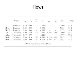
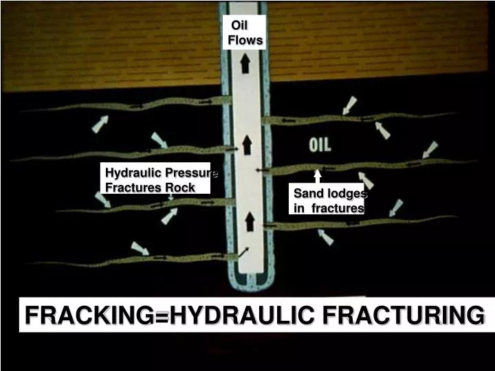
Oil Flows. Hydraulic Pressure Fractures Rock. Sand lodges in fractures. FRACKING=HYDRAULIC FRACTURING. The Marcellus Shale Formation: Large Area Shallow Depth Lots of Gas Thin formation Tight Rock Jointed formation. http://geology.com/articles/marcellus-shale.shtml.

E N D
Oil Flows Hydraulic Pressure Fractures Rock Sand lodges in fractures FRACKING=HYDRAULIC FRACTURING
The Marcellus • Shale Formation: • Large Area • Shallow Depth • Lots of Gas • Thin formation • Tight Rock • Jointed formation http://geology.com/articles/marcellus-shale.shtml
Marcelus and Utica Shale are Tight Rocks • Marcellus shale is “tight”, meaning not many small cracks between joints, so the gas trapped in the rock needs help to be released to the surface: artificial fracture is the solution. • Open joints using “hydraulic fracturing” or fracking.
“Horizontal” Drilling and Fracturing Not to scale ~ 3500 feet Cap rock ~ 100 feet Pay zone Cap rock
A Typical Drilling Pad Let’s watch a movie to see what happens from such a site Pumps and Power Drill Rig Drilling Mud Lagoon Injection Water and Flowback Lagoon http://www.glossary.oilfield.slb.com/
More Than One Well per Pad Well (6 here) Hydraulic fracture ~100’s of feet Pad Not to Scale many 1000’s of feet
Direction of max horizontal stress Geology controls the arragement
Example: Dallas/Fort Worth Airport Property, Barnett Shale Play • 53 pads on 18,076 acres • Almost complete • coverage • Patchwork, mostly ideal • units • One developer
Some chemicals used in the procedure Proppant: Particles, like sand, transported into the fractures to keep them open after fracturing pressure release. Gelling Agents: Increase fluid viscosity to help proppant transport. Biocides: Kill bacteria that harm the gelling agents. Breakers: Decrease viscosity of the fracturing fluid, after the fracturing process, to improve flowback. Anti-Corrosives: Protect metallic elements in the well. Friction Reducers: Allow high pressures and flow rates. Acid : Clean out perforations, well, fractures http://www.epa.gov/OGWDW/uic/pdfs/cbmstudy_attach_uic_ch04_hyd_frac_fluids.pdf http://www.earthworksaction.org/hydfracking.cfm
Additives to Fracturing Fluids From NYS DEC’s SGEIS, 2009
PROBLEM • When the fracturing process is completed, the pressure is released, and much of the fracturing fluid backflows to the wellhead*. • The backflow is: • highly saline; • contain some heavy metals (e.g. barium, strontium); • Toxic fluid additives; FLUID Recycling can ameliorate this problem but more research is needed to achieve good results
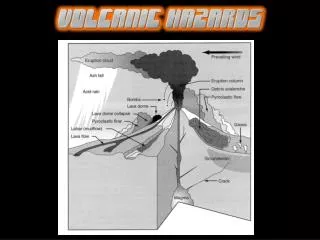
Potential Problems • Contamination of ground water and surface water by fracturing fluids • Water leaks • Gas leaks • Interconnection of aquifers produced by fractures and alteration of the underground rock layers • Destruction of the confining nature of common confined aquifers in SE Ohio. • Lack of good models to predict expected impacts, more research is needed to understand water and gas circulation during and after exploitation. • For zones that are impacted (contaminated water wells, etc.), for how long are they going to be impacted? Who is going to supply clean water to the affected users after exploitation ends?