Download
1 / 18
250 likes | 599 Views
Strengths of Adhesive Joints. Definition . The final test for any adhesive is that it should give joints which are strong and durable.

E N D
Definition • The final test for any adhesive is that it should give joints which are strong and durable. • Although ways do exist of assessing the quality of joints by ultrasonic non-destructive testing, the ultimate test is to measure the force or energy needed to break a joint.
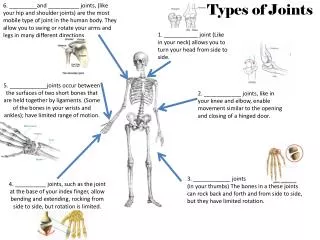
Test specimen • Many types of joints are available and illustrated in thenFigure are single and double laps, cylindrical butts, and 90˚ peels.
Principle modes of fracture • There are three principal modes of fracture: • Mode I is due to peel or cleavage forces. • Mode II is a shearing mode, • Mode III is a shearing mode but here shearing is in torsion around an axis instead of along a plane.
Adhesives, shear and peel • In general, rigid adhesives are strong in shear but weak in peel, whereas • Rubbery adhesives are resistant to peel but creep in shear. • Rubber toughening of modern structural adhesives improves their peel strength.
Single lap test, reproducibility • Important considerations: (i) Size of the adherends and amount of overlap. (ii) Control of the thickness of the adhesive layer . This can be done by the use of jigs, or by adding small glass spheres (Ballotini) or incorporating wires (fuse wire or fishing line). Commercial film adhesives may contain knitted or woven fabrics known as carriers (UK) or scrims (USA). Stronger joints are obtained with thin glue-lines; optimum practical glue-line thickness would be 0.10-0.15 mm. (iii) Conditions of cure such as time, temperature, application of pressure. (iv) Ageingof joints prior to testing, e.g. in ambient or hot and humid conditions. (v) Jointtestingconditions are most commonly ambienttemperaturesand humidities and in a mechanical testing instrument. constant crosshead speed, usually of a few mm per minute with single lap joints, slipping of the adherendsin the jaws can mean that the set crosshead speed is greater than the rate at which the joints are strained. In hydraulic instruments a constant loading rate (kN min - ') can be used.
Modes of Failure • Failure can be by • interfacial/ adhesive failure, • cohesive failure of the adhesive, or • failure of an adherend. • In some cases there is a mixture of failure modes. • Interfacial failure indicates that an improved surface treatment is needed, and • if failure is cohesive the adhesive may need strengthening with a mineral filler.
How does the strength of lap joints vary with width and overlap? • A simple view might be that strength will be proportional to area but this is not the case. Wang, Ryan and Schonhorn measured the strengths of some joints in aluminium etched in chromic acid and bonded with an epoxideadhesive with an aliphatic amine hardener. • Strength was proportionalto joint width, but a plot of strength against overlap tended to level out as overlap increased. strength is independent of bonded area.
Stress Propagation along the ovelap • The stress in each adherend falls to zero at the free-end of the overlap, and hence the strain decays in a proportionate manner.
Deformation during test and stress concentration The mean shear stress is 8.96MPa, but this is concentrated to give a maximum of 96.5MPa very near the ends. The central region bears no loads
PEEL TESTING • Peeling a flexible tape from a rigid substrate, to which it had been bonded using a flexible adhesive. • The peeling force P is assumed to produce a steady rate of peeling.
PEEL TESTING Strength improvement obtains by: (i) increasing adhesive flexibility, i.e. reducing Y; (ii) increasing the modulus of the tape E; (iii) increasing tape thickness; (iv) increasing the thickness of the adhesive. • Kaelble’s treatment assumes that the tape is pivoted about the point O, such that there is a cleavage force to the right of O, and a compressive force just to the left.
PEEL TESTING, 90˚ and 180 ˚ where m is the sum of cleavage moments and I is the moment of inertia of the tape section.
No testing Machines,Boeing Wedge Test • The Boeing wedge test : • Two stiff adherends are bonded together, leaving a non-bonded section at one end; inserting a film of polyolefin or PTFE can be useful here. • A metal wedge is forced into this to initiate a crack. • The joint is then exposed to some hostile condition such as warm, wet air, and the increase in crack length is measured. • It is particularly useful for examining the effect of surface treatments on wet-durability. • Crack length can be measured by holding the sample up to light and using a plastic ruler.
TACK • Tack is the ability to bond under conditions of light pressure and short time, and can be measured by • the time needed for a ball or cylinder to roll down an inclined plane coated with the adhesive, or by a probe method. • Here a probe is lowered at a constant speed onto the adhesive coated surface, and, after a fixed dwell time, the force needed to remove it is measured.
Tack force, critical surface tension and dwell time tack force increases with the critical surface tension of the probe surface, and with dwell time
REPORTING THE RESULTS • It is best to report the strength of a lap joint as the force needed to break it in newtons, at the same time specifying the joint geometry. • Example: • The adherends were of aluminiumalloy, which had been degreased and etched in chromic acid, and bonded with an epoxide adhesive into 25mm square lap joints, which were cured for 3 h at 80 ˚C. They were tested at a crosshead speed of 6mmmin-', and all failed cohesively. • Joint strengths (kN): 17.3, 18.7, 15.8, 20.4, 17.8, 20.4, 14.2, 15.8. Mean = 17.5 kN. Standard deviation = 2.2 kN or 12%.