Download
1 / 32
360 likes | 790 Views
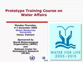
TRAINING COURSE on EXPERIMENTAL MICRODOSIMETRY. Principle of silicon - based microdosimetry Stefano Agosteo 1,2 , Andrea Pola 1,2 1 Politecnico di Milano, Dipartimento di Energia, piazza Leonardo da Vinci 32, 20133 Milano, Italy .

E N D
TRAINING COURSE on EXPERIMENTAL MICRODOSIMETRY Principle of silicon-basedmicrodosimetry Stefano Agosteo1,2,Andrea Pola1,2 1Politecnicodi Milano,Dipartimento di Energia, piazza Leonardo da Vinci 32, 20133 Milano, Italy. 2Istituto Nazionale di FisicaNucleare, Sezione di Milano, via Celoria 16, 20133 Milano, Italy. uthorname, Institute
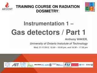
+ - P zone Depeleted zone N zone
SILICON MICRODOSIMETRY PN diodes [1]J. F. Dicello, H. I. Amols, M. Zaider, and G. Tripard, A Comparison of Microdosimetric Measurements with Spherical Proportional Counters and Solid-state Detectors, Radiation Research 82 (1980) 441-453. [2] M. Orlic, V. Lazarevic, and F. Boreli, Microdosimetric Counters Based on Semiconductors Detectors, Radiat. Prot. Dosim. 29 (1989) 21-22. [3] A. Kadachi, A. Waheed, and M. Obeid, Perfomance of PIN photodiode in microdosimetry, Health Physics 66 (1994) 577-580. [4] A. Kadachi, A. Waheed, M. Al-Eshaikh, and M. Obeid, Use of photodiode in microdosimetry and evaluation of effective quality factor, Nuc. Instrum. Meth. A404 (1998) 400-406. The differencesfrom the linealenergyspectrameasuredwith the TEPC (TissueEquivalentProportionalCounter) weremainlyascribedto the shape and the dimensionsof sensitive volumes Complex charge collection process
INTRODUCTION (I) • The micrometric sensitive volumes which can be achieved with silicon detectors led these devices to be studied as microdosimeters. • coupled to TE converters, microdosimetry of neutron fields; • bare (no converter): they can be used for measuring the quality of radiation therapy beams and SEE assessment. Spectrum of the energy imparted per event in silicon Tissue-equivalent converter Microdosimetric spectrum in tissue Data Analysis Spectroscopy Chain Silicon device Analytical corrections
INTRODUCTION (II) • Advantages: • wall-effects avoided; • compactness; • cheapness; • transportability; • low sensitivity to vibrations; • low power consumption.
INTRODUCTION (III) • Problems: • the sensitive volume has to be confined in a region of well-known dimensions (field-funnelling effect); • corrections for tissue-equivalency (energy dependent); • correction for shape equivalency of the track distribution (for TEPC comparison); • angular response; • the electric noise limits the minimum detectable energy (high capacitance); • the efficiency of a single detector of micrometric dimensions is very poor (array of detectors); • radiation hardness.
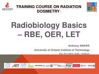
P-Layer Recoil proton Field Funneling Effect Depletion Layer 2 µm @ 2V N+ THE FIELD-FUNNELING EFFECT • FFE: a local distortion of the electric field in the sensitive zone, induced by high-LET particles, which leads to charge collection outside the depleted region. • Example: p-n diode coupled to a polyethylene converter, irradiated with monoenergetic neutrons: Depletion layer thickness: 2 m @ 2 V Active thickness: ~ 12 m
+ E-field - THE FIELD-FUNNELING EFFECT: SOLUTIONS • Array of diodes fabricated using the silicon on insulator (SOI) technology (Rosenfeld et al.). • This technique allows to obtain sensitive volumes of well defined dimensions, independent of the field funnelling effect; • Different structures with a sensitive volume 2, 5 and 10 μm in thickness were fabricated. • The absorbed dose distributions from different neutron fields were compared to simulations performed with the GEANT code and measurements with a standard TEPC, resulting in a satisfactory agreement. Al Al 1 um N+ P+ 2 um Si Substrate SiO2 ~ 10-20 um Allfigures in this slide Courtesyof A. Rosenfeld, WollongongUniversity, Australia
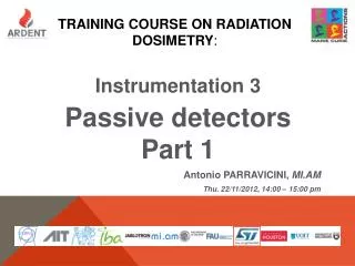
Sensitive area: 1 mm2 E thickness: ~1.9 m E thickness: ~ 500 m Echarge collection THE FIELD-FUNNELING EFFECT: SOLUTIONS • Monolithic silicon telescope(ST-Microelectronics, Catania, Italy): • the p+ cathode acts as a “watershed” for charge collection, thus minimizing the FFE.
EFFECTS ON SILICON AND DOPANTS • Contributions of nuclear reactions induced on a p-i-n diode by thermal and fast neutrons were measured in the past. • secondary particles from neutron reactions on 10B were observed (rate 2.210-6 s-1per unit fluence rate of thermal neutrons vs. 10-5 s-1 recoil-protons); • secondary particles generated by fast neutrons on silicon were also observed. • 28Si(n,p)28Al (Eth 4.0 MeV); • 28Si(n,)25Mg (Eth 2.75 MeV). • Further investigation is necessary for new devices. • Only 11B was implanted in the silicon telescope: • During irradiation on the thermal column of the TAPIRO reactor, no events from 10B(n,)7Li were observed.
E r Si MESA MICRODOSIMETERS • 3D silicon mesa p-n junction array with internal charge amplification produced at UNSW SNF. Single mesa 3D SV All figures in this slide Courtesy of A. Rosenfeld, Wollongong University, Australia
SEGMENTED SILICON TELESCOPE • In the following the main problems related to a silicon microdosimeter will be discussed mainly referring to the: • segmented silicon telescope: • constituted by a matrix of cylindrical ∆E elements (about 2 µm in thickness) and a single residual-energy E stage (500 µm in thickness); • the nominal diameter of the ∆E elements is about 9 μm and the width of the pitch separating the elements is about 41 µm. • more than 7000 pixels are connected in parallel to give an effective sensitive area of about 0.5 mm2. • minimum detectable energy is limited to about 20 keV by the electronic noise. • the ∆E stage acts as a microdosimeter and the E stage plays a fundamental role for assessing the full energy of the recoil-protons, thus allowing to perform a LET-dependent correction for tissue-equivalency.
Recoil-protons Recoil-protons • May be due to: • Track length distribution; • Charge sharing. Contribution of about 5.5% Secondary electrons SEGMENTED SILICON TELESCOPE: SCATTER-PLOT • 2.7 MeV neutron irradiation of the telescope coupled to A-150 plastic; • The signals from the E and the E stage were acquired with a 2-channel ADC in coincidence mode.
Recoil-protons SEGMENTED SILICON TELESCOPE: SIMULATION • The response of a cylindrical element of the ∆E stage was simulated with a MC algorithm; • The algorithm takes into account the geometrical structure of the telescope, but does not reproduce border effects. • Secondary electrons from photon interactions on the materials surrounding the detector were not accounted for. Recoil-protons Calculated contribution of about 5% due to the track length distribution! Charge sharing can be neglected
TISSUE-EQUIVALENCE AND GEOMETRIC CORRECTIONS • In order to derive microdosimetric spectra similar to those acquired by a TEPC, corrections are necessary; • Tissue equivalence: • a LET-dependent tissue equivalence correction can be assessed through a telescope detector: • by measuring event-by-event the energy of the impinging particles; • by discriminating the impinging particles. • Shape equivalence: • basing on parametric criteria from the literature, the lineal energy y was calculated byconsidering an equivalent mean cord length.
TISSUE-EQUIVALENCE CORRECTION Analytical procedure for tissue-equivalence correction: Scaling factor : stopping powers ratio Energy deposited along a track of length l by recoil-protons of energy Ep in a tissue-equivalent E detector
the thickness of the E stage limits the TE correction to recoil-protons below 8 MeV (alphas below 32 MeV) TISSUE-EQUIVALENCE CORRECTION The scaling factor depends on the energy and type of the impinging particle E stage of the telescope and ∆E-E scatter-plotallow an energy-dependent correction for protons Electronsrelease only part of their energy in the E stage ELECTRONS: average value over a wide energy range (0-10 MeV) = 0.53
SHAPE ANALYSIS • The correcting procedure can be based on cord length distributions, since ∆E pixels are cylinders of micrometric size in all dimensions (as the TEPCs).; • This correction is only geometry-dependent (no energy limit).
COMPARISON WITH A CYLINDRICAL TEPC • The microdosimetric spectra were compared to the one acquired with a cylindrical TEPC at the same positions inside a PMMA phantom. • L. De Nardo, D. Moro, P. Colautti, V. Conte, G. Tornielli and G. Cuttone, RPD 110 (2004) • Proximal part and across the SOBP: • Corrections: • Protons cross both the E and the E stage. • Tissue- equivalence: • a scaling factor was applied: • Shape equivalence: • by equating the dose-mean energy imparted per event for the two cylindrical sites: =
DISTAL PART OF SOBP • Distal part of the SOBP: most of protons stop in the E stage • An energy dependent correction for TE can be applied from the event-by-event information from the two stages:
Constant scaling factor Energy-dependent correction DISTAL PART OF SOBP
ENERGY THRESHOLD IMPROVEMENT The main limitation of the system is the high energy threshold imposed by the electronic noise. New design of the segmented telescope with a ∆E stage with a lower number of cylinders connected in parallel and an E stage with an optimized sensitive area • Decrease the energy threshold below 1 keV μm-1 • Optimize the counting rate of the two stages A feasibility study with a low-noise set-up based on discrete components was carried out in order to test this possibility
Lineal energy threshold ≈ 0.6 keV μm-1 ENERGY THRESHOLD IMPROVEMENT A telescope constituted by a single ΔE cylinder coupled to an E stage was irradiated with βparticles emitted by a 137Cs source.
CONCLUSIONS • Silicon detectors show interesting features for microdosimetry, anyway still some problems have to be solved: • electronic noise (minimum detectable lineal energy); • radiation hardness when exposed to high-intensity hadron beams.
By equating the dose-mean energy imparted per event for the two different shapes considered: = SHAPE ANALYSIS The equivalence of shapes is based on the parametric criteria given in the literature(Kellerer). By assuming a constant linear energy transfer L: Dimensions of ∆E stages were scaled by a factor η … … the lineal energy y was calculated by considering an equivalent mean cord length equal to:
PMMA phantom PMMA foils Detector + Mylar Front-end electronics IRRADIATIONS AT THE CATANA FACILITY • The segmented silicon telescope was irradiated inside a PMMA phantom exposed to the 62 MeV proton beam at the INFN-LNS CATANA facility.
PROXIMAL AND ACROSS THE SOBP Constant TE scaling factor
DISTAL PART OF THE SOBP Event-by-event TE correction!!!