Download
1 / 27
270 likes | 377 Views
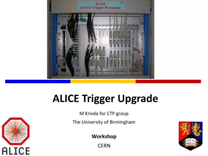
M Krivda for CTP group The University of Birmingham. ALICE Trigger Upgrade. Workshop CERN. Content. ALICE after LS2 Trigger requirements Trigger architecture Implementation Summary. Current ALICE. Limited readout rate capability pp mnimum bias: ~ 1kHz

E N D
M Krivda for CTP group The University of Birmingham ALICE Trigger Upgrade Workshop CERN
Content ALICE after LS2 Trigger requirements Trigger architecture Implementation Summary
Current ALICE Limited readout rate capability ppmnimum bias: ~ 1kHz Pb-Pb minimum bias: ~500 Hz
ALICE upgrade after LS2 Target Luminosity: Pb-Pbrecorded luminosity≥ 10 nb-1 (50 khz) pp (@5.5 Tev) recorded luminosity ≥ 6 pb-1 ( 200kHz) Minimum bias physics : gain a factor 100 Triggered physics: gain a factor 10 Upgrade the ALICE readout systems (TPC, muons) Upgrade online systems (CTP, DAQ) Improve vertexing and tracking at low pTNEW ITS
ALICE trigger challenges Select different physics Different triggering detectors Optimise for different running scenarios – pp, pA, AA – with different interaction rates Optimise use of detectors with Continuous readout Widely different busy times Different latency times Different technologies (TTC and GBT) Special triggers (calibration, control, debugging)
Trigger Architecture I One level synchronous trigger followed by message Trigger latency optimised for every detector Grouping of readout detectors possible Trigger generation and distribution: Central Trigger Processor (CTP) : receives signals from triggering detectors, makes decision and send triggers via LTU to detectors Generates software/calibration triggers Local Trigger Unit (LTU): Interface between CTP and detector Generates TTC or GBT triggers Emulates CTP for development and debugging of detectors Common Readout Unit (CRU): interface between On Detector electronics, DAQ and CTP
Trigger architecture II Transmission latency depends on the location of CRU
Triggering detectors • ~ 8 triggering detectors • Three different latencies (levels)
Readout Parameters Mixture of busyless and busy detectors TTC and GBT trigger distribution
BUSY handling Busy for upgraded detectors status signal detectors might receive triggers, even though they might not be ready to process them in that case, detectors need to send acknowledge of trigger with information that no data will be sent Busy for non upgraded detectors Busy propagated with minimal latency, e.g. by electric cable CTP covers busy propagation from FE to CTP
Software triggers Heartbeat trigger: Specific trigger issued by CTP at appropriate ORBIT/BC Reduces trigger data bandwidth Carrying commands and specific synchronization information Used by detectors – create “heartbeat events” sent via output links Used by processing nodes – data segmentation, fault finding, recovery procedures, … Calibration triggers Control triggers (Start of Data, End of Data)
Hardware options Advanced Telecommunications Computing Architecture (ATCA) off the shelf modification of existing board Custom boards VME based (continuation of run2 trigger design)
ATCA CTP example ATCA crate with 3 TELL40 boards Board 1: AMC CTP AMC LHC interface AMC TFC (Time and Fast Control) AMC TTC (LTU: Trigger to Detectors) Board 2: 4 x AMC (LTU: Triggers to Detectors) Board 3: 4 x AMC (LTU: Triggers to Detectors)
ATCA CTP example: latency 1.5 BC synchronisation of trigger inputs 2 BC trigger decision/formatting data 140 ns serialisation/de-serialisation over backplane 1 BC for LTU 166 ns for GBT downstream delay TOTAL: ~ 420 ns + cable
ATCA off the shelf ATCA off shelf boards TELL40 + AMC40 Custom mezzanine for electrical trigger inputs Mezzanine for TTC interface Problem with achieving low latency Estimated latency over backplane ~ 140 ns (3.2 Gb/sec) 10 G links not available at current version of TELL40 Magnetic field ~ 10 mTesla– discussion ongoing Radiation – Total Ionisation Dose ~ 5x10⁻³krad
Custom boards: VME Continuation of Run2 electronics VME: Mechanical support Power supply Board communication via fast links
Distribution of trigger signals Custom protocol Electrical or optical transmission Daisy – chain of FI/FO boards in case that more than one FI/FO board is necessary Detector 1 FI/FO board 2 FI/FO board n LM01 board FI/FO board 1 Detector 2 . . . . . . . . . . Detector 24 96 trigger inputs TTC GBT GBT
Summary Major upgrade of ALICE detector, for installation in 2018/19, to cope with Pb-Pb collisions at high rates CTP: Minimum bias trigger High pt calorimeter triggers Special triggers (Calibration, control, debugging) Several options for implementation considered: decision to be taken at beginning of 2015
Future Plans 2013-2014 – Long Shutdown 1 (LS1) Completion of detector (TRD, Calorimeters) CTP upgrade (see Marian Krivda’s talk tomorrow) 2015-2017 10 x increase in statistics in Pb-Pb at s =5.5 TeV, i.e 1nb-1 to be collected 2018 ALICE upgrade – Long Shutdown 2 (LS2) High precision measurements of rare probes at low pT: Increase rate capability – continuous readout and new online systems (for CTP see MK talk tomorrow) Improve vertexing and low pT tracking – new silicon vertex tracker 2019-2021 (Ar-Ar,p-Pb,Pb-Pb) 10nb-1
Alice Running Conditions Pb-Pb: luminosity:≥ 10 nb-1 , 50kHz (i.e. L = 6x1027 cm-1s-1) pp: Luminosity: ≥ 6 pb-1
ALICE focus after LS2 • Precision measurement of the QGP parameters at b = 0 • to fully exploit scientific potential of the LHC– unique in: • large cross sections for hard probes • high initial temperature • Main physics topics, uniquely accessible with the ALICE detector: • measurement of heavy-flavour transport parameters: • study of QGP properties via transport coefficients (/s, q) • measurement of low-mass and low-pT di-leptons • study of chiral symmetry restoration • space-time evolution and equation of state of the QGP • J/, ’, and cstates down to zero pT in wide rapidity range • statistical hadronizationversus dissociation/recombination ˆ
Detector Dead Time • Dead Time depends on: • Readout time • Multi-event buffer Detector Dead Time: average time of BUSY after valid trigger.
Trigger signals run1/2 & run3 L1 L1 L0 L2y/n L0 L2y/n tL2 tL2 Run1/2 tL1 tL1 trigger time-out trigger time-out trigger signal either LM, L0 or L1 trigger signal either LM, L0 or L1 ttrigger Run3