Download
1 / 47
470 likes | 554 Views
Whisper 200 Analysis and Remediation. Phase III Presentation Group 7 Thomas Kudej Marko Sutovic Timothy Smith. Group Members. Advisor. Professor Basu. Thomas Kudej. Timothy Smith. Marko Sutovic. Presentation Outline. Project Objective Background Phase I-II Phase III CFD

E N D
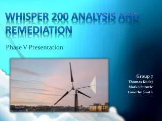
Whisper 200 Analysis and Remediation Phase III Presentation Group 7 Thomas Kudej Marko Sutovic Timothy Smith
Group Members Advisor Professor Basu Thomas Kudej Timothy Smith Marko Sutovic
Presentation Outline • Project Objective • Background Phase I-II • Phase III • CFD • Initial Conditions • Modeling and Results • Experiment • Anemometer Program • Procedure • Results • Budget • Gantt Chart • Nugget Chart • Phase IV - Plan of Action • Questions?
Project Objectives • Whisper 200 Wind Turbine • Find a Suitable Location for The Whisper 200 • Acquire Wind Velocity and Directional Data • Prove Current Location is Inadequate • Satisfy Power Generation Requirements
Summary of Phase I • Original Problem Objective • Examined Wind Turbine • Restructure Overall Project Objective • Observed Wind Turbine Behavior • Whisper 200 Performance • Developed Conceptual Designs • Several Designs to Fix the Problem
Conceptual Designs Proposed • Conceptual Designs Proposed • Stability of the Wind Turbine • Noise Cancellation Devices • Use of Isolators to Support The Wind Turbine • Removal of Aesthetic Lip on Babbio • Move Turbine to Different Location • Funnel Air Towards Turbine
Summary of Phase II • Phase II Objectives • Determining the Power Output of a Wind Turbine as a Function of • Wind Speed • Wind Direction • Wind Characteristics • Determining Superior Roof-top Location for the Whisper 200
Conceptual Designs • Wind Fan Power Output • Purpose • Results
Conceptual Design Analysis • Analyzing Results From Experiment • Obstructions on the Babbio Center Roof-top are Affecting Power Production • Building Design and Structure • Proposed Solution • Relocation of Wind Turbine • Wind Velocity and Directional Testing • Plan of Action for Testing
Computational Fluid Dynamics Air Flow Analysis • Using Cosmos Floworks, we were able to simulate the air flow in real world conditions and analyze the effects at each targeted location. • External flow parameters were used instead of internal flow. • The locations modeled in Solid Works were: • Babbio Center • Howe Center • Castle Point Apartments • Each model included their respective rooftop structures to determine the effect they could be having on the directional component of air flow. • Initial conditions and Boundary conditions were chosen to define the problem
CFD – Initial Conditions • Our initial conditions were chosen to simplify the model and decrease solving time as well as give us a fairly accurate portrayal of what is occurring. • Air was selected as the working fluid • Initial Ambient Conditions • Pressure at 101 kPA • Temperature at 273.5 K • The velocity of the air in the X direction was set as 5m/s • Through research, the average wind speed in the NYC area was 4-5 m/s • Start up speed of the Whisper 200 is 3.1 m/s
CFD – Boundary Conditions • Only one boundary condition was defined • Walls of each structure • The walls were defined as ideal walls which modeled them as adiabatic and frictionless. • We chose not to model the walls as real because our analysis centered on the effect of each buildings geometry on the wind flow. • Prove why Babbio is currently not sufficient • Determine location where wind conditions are suitable • Heat transfer coefficient, wall temperature and roughness factor were all negligible in our assumptions.
CFD – Babbio Center Model of the Babbio Center roof top
CFD – Babbio Center Air flow over the roof
CFD – Babbio Center North face of the Babbio Center – Notice the wake region in the upper right.
CFD – Babbio Center Wind coming in from the North-West
CFD – Howe Center Model of Howe Center
CFD – Howe Center Wind flow over Howe
Anemometer Program • Anemometer lacked a display device to show analytical data. • DAQ from Design II Lab enabled the reading of voltage outputs from the sensors. • LabView was utilized to create a user interface and log output feature. • Anemometer was calibrated using Fluids Lab wind tunnel. • See Appendix slides A&B for full program and interface.
Procedure • Readings were taken with the Anemometer at 8 locations. • Babbio, CPA, Howe, and River Lot • All readings were taken within a two hour time period, as to reduce the effect of changing weather conditions. • Experiment was repeated on multiple days. • Results were analyzed to determine the best placement location for the Whisper 200.
Measurements and Results • Sample was taken at Babbio Location A (original location) on Day 1 between 1:35pm and 1:45pm. • Average Wind Velocity was measured to be 3.6875m/s. • Wind Direction was very sporadic. • Each location was analyzed in this way on three separate days. (See Appendix slides for data)
Measurements and Results • Sample was taken at CPA Location B (optimal location) on Day 1 between 3:00pm and 3:10pm. • Average Wind Velocity was measured to be 4.0408m/s. • Wind Direction was conclusively consistent. • After analysis, this location was chosen as the most optimal for the Whisper 200, due to its constant wind direction and reliable wind velocity.
Looking at the Future • Phase IV • Determine the power output of the wind turbine at new location • Install data logger to see how much is being produced. • How much money is saved? • Monitor the wind turbine and see if any noise or vibration issues arise • Use gathered data to tweak the design and improve energy production. • Restrict the turning mechanism • Develop channels to funnel the air
Title: Whisper 200 Analysis and RemediationTeam Members: Marko Sutovic, Timothy Smith, Thomas KudejAdvisor: Dr Basu, Dr Prasad Project #: 7 Date:12/15/09 ME 423 Phase III Nugget Chart– Engineering Design