Download
1 / 47
470 likes | 676 Views
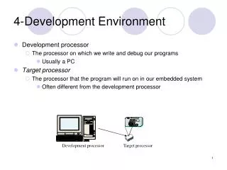
The Processor: Multicycle Implementation. Reminder: Single-Cycle Datapath. Multicycle Approach. Break up the instructions into steps, each step takes a cycle balance the amount of work in cycles only one major functional unit is used in each cycle At the end of each cycle

E N D
The Processor: Multicycle Implementation
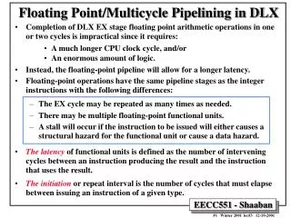
Multicycle Approach • Break up the instructions into steps, each step takes a cycle • balance the amount of work in cycles • only one major functional unit is used in each cycle • At the end of each cycle • store values for use in later cycles • introduce additional “internal” registers • We will be recycling functional units • ALU used to compute branch address and to increment PC • The same memory used for instruction and data • We will use finite state machine for control
Multicycle Implementation • buffer registers between functional units which will be updated every clock cycle • IR: Instruction register • MDR: Memory Data register • Aand B registers to hold register operand values read from register file • ALUOut: to hold output of ALU
Handling PC • Multiplexor for selecting the source for the PC • ALU output after PC+4 • ALU output after branch target address calculation • New address with jump instructions (26 bits of IR) • Control signals for writing PC • Unconditionally after a normal instruction and jump - PCWrite • Conditionally overwritten if a branch is taken • When PCWriteCond and zero are asserted, the branch address at the output of ALU is written into the PC.
PCWriteCond zero PC+4, jump address, branch address Handling PC PCWrite PC 1 Address 0 Memory MemData IorD write data from ALUOut
Five Execution Steps • Instruction Fetch • Instruction Decode and Register Fetch • Execution, Memory Address Computation, or Branch Completion • Memory Access or R-type instruction completion • Write-back stepINSTRUCTIONS TAKE 3 - 5 CYCLES!
Step 1: Instruction Fetch • Use PC to get the instruction and put it in IR. • Increment the PC by 4 and put the result back in the PC. • Can be described succinctly using RTL IR <= Memory[PC]; PC <= PC + 4;The ALU is used for incrementing PC • Control signalsMemRead = ? IRWrite = ? PCWrite = ?IorD = ? ALUSrcA = ? ALUSrcB = ?? ALUOp = ?? PCSource = ??
Step 2: Instruction Decode & Register Fetch • Read registers rs and rt in case we need them • Compute the branch address in case the instruction is a branchA <= Reg[IR[25-21]]; B <= Reg[IR[20-16]]; ALUOut <= PC + (sign-extend(IR[15-0])<<2); • We aren't setting any control lines based on the instruction type yetALUSrcA = ?(PC)ALUSrcB = ?? (sign-extended & shifted offset)ALUOp = ??(add)
Step 3 (Instruction Dependent) • ALU performs for one of the four functions • Memory Reference: ALUOut <= A + sign-extend(IR[15-0]); ALUSrcA = ?, ALUSrcB = ??, ALUOp = ?? • R-type: ALUOut <= A op B; ALUSrcA = ?, ALUSrcB = ??, ALUOp = ?? • Branch:if (A == B) PC <= ALUOut; ALUSrcA = ?, ALUSrcB = ??, ALUOp = ??, PCWriteCond = ?, PCSource = ?? • Jump:PC <= PC[31:28]||(IR[25:0]<<2) PCWrite = ?, PCSource = ??
Step 4 (R-type or Memory-Access) • Load and store instructions access memory • lw: MDR <= Memory[ALUOut];MemRead = ?, IorD = ? • sw: Memory[ALUOut] <= B;MemWrite = ?, IorD = ? • R-type instructions finishReg[IR[15-11]] <= ALUOut; RegDst = ?, RegWrite = ?, MemtoReg = ?
Write-Back Step • Memory read completion step • Reg[IR[20-16]] <= MDR;RegDst = ?, RegWrite = ?, MemtoReg = ? What about all the other instructions?
Instructions in Multicycle Implementation • Loads: 5, Stores: 4, ALU Instructions: 4, Branch: 3, Jump: 3 • Example: From SPECINT2000, instruction mix: • 25 % loads (1% load byte + 24% load word) • 10% stores (1% store byte + 9% store word) • 11 % branches (6% beq + 5% bne) • 2 % jumps (1% jal + 1% jr) • 52% ALU operations • CPI = formula = 4.12
Example • How many cycles does it take to execute this code?lw $t2, 0($t3) lw $t3, 4($t3) beq $t2, $t3, Label #assume not taken add $t5, $t2, $t3 sw $t5, 8($t3)Label: ... • What exactly is happening during the 8th cycle of execution? • In what cycle does the actual addition of $t2 and $t3 take place?
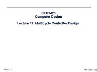
Implementing the Control • A control unit that will • assert control signals at the right time • determine the next step • Value of control signals is dependent upon: • which instruction is being executed • which step is being performed (implies sequential logic) • Two specification methods • State diagrams • Microprogramming • Implementation can be derived from this specification
Review: Finite State Machines • Finite state machines: • a finite set of states and • next state function (determined by current state and input) • output function (determined by current state and possibly input) • We’ll use a Moore machine (output based only on current state)
Finite State Machines Inputs Mealy Outputs Output Function Next State Function Combinational Network State Elements Next state state clk Output Function MooreOutputs Combinational Network
MemRead ALUSrcA = 0 IorD = 0 IRWrite ALUSrcB = 01 ALUOp = 00 PCWrite PCSource = 00 S0 start ALUSrcA = 0 ALUSrcB = 11 ALUOp = 00 S1 op = ‘lw’ or ‘sw’ op = R-type op = ‘j’ op = ‘beq’ Branch FSM Jump FSM R-type FSM Memory Reference FSM State Diagram for Fetch & Decode
From state S1 ALUSrcA = 1 ALUSrcB = 10 ALUOp = 00 S2 Op = ‘lw’ or ‘sw’ memory address calculation lw sw S3 MemRead IorD = 1 S5 MemWrite IorD = 1 memory access memory access S4 memory read completion RegDst = 0 RegWrite MemtoReg = 1 To state S0 State Diagram for Memory-Access
From state S1 Op = R-type S6 ALUSrcA = 1 ALUSrcB = 00 ALUOp = 10 Execution R-type completion S7 RegDst = 1 RegWrite MemtoReg = 0 To state S0 State Diagram for R-type
From state S1 Op = beq ALUSrcA = 1 ALUSrcB = 00 ALUOp = 01 PCWriteCond PCSource = 01 S8 Branch completion To state S0 State Diagram for Branch
From state S1 Op = j PCWrite PCSource = 10 S9 Jump completion To state S0 State Diagram for Jump
MemRead ALUSrcA = 0 IorD = 0 IRWrite ALUSrcB = 01 ALUOp = 00 PCWrite PCSource = 00 S0 S1 ALUSrcA = 0 ALUSrcB = 11 ALUOp = 00 start Op = j Op = beq Op = R-type Op = ‘lw’ or ‘sw’ S9 S2 ALUSrcA = 1 ALUSrcB = 10 ALUOp = 00 ALUSrcA = 1 ALUSrcB = 00 ALUOp = 10 ALUSrcA = 1 ALUSrcB = 00 ALUOp = 01 PCWriteCond PCSource = 01 PCWrite PCSource = 10 S8 S6 sw lw S7 S3 S5 MemRead IorD = 1 MemWrite IorD = 1 RegDst = 1 RegWrite MemtoReg = 0 S4 RegDst = 0 RegWrite MemtoReg = 1 Complete State Diagram How many state bits are needed?
Implementing the Control outputs datapathcontrol outputs Combinationalcontrol logic inputs state next state FFs inputs from instruction Moore or Mealy machine?
Exceptions or Interrupts • Unintentional change of normal flow of instructions • Exception is an unexpected event from within the processor, e.g arithmetic overflow. • An interrupt may come from outside of the processor. • These terms are observed to be used interchangeably (IA32 uses interrupts for both) • Our simplified MIPS architecture can generate two exceptions: • Arithmetic overflow • Undefined instruction.
When an Exception Occurs 1/2 • Exception program counter (EPC) • PC of the current instruction (i.e. PC-4) in EPC • Transfer the control to OS at some specified address. • The OS does what needs to be done, it either • Stops the execution of the program and reports an error • Provides a service to the user program (e.g a predefined action to an overflow) and return to the point of origin of exception using EPC
When an Exception Occurs 2/2 • The OS must know the reason for the exception • An exception is handled using two approaches: • cause registercontainsthe reason for exception (MIPS). • Vectored interrupt: For each interrupt type, a separate vector is stored and each interrupt vector targets at the appropriate piece of code.
Vectored Interrupts For each cause of the interrupt, the control goes toa different location in memory to handle the exception
How MIPS Handles Exceptions • Registers • EPC • Cause register: individual bits are used to encode the cause of exceptions (e.g. 0 in the LSB for undefined instruction 1 for overflow) • Control Signals • CauseWrite • EPCWrite • IntCause: 1-bit signals to set the appropriate bit of Cause register • Exception address: • 0x8000 0180 (SPIM uses 0x8000 0080)
0x8000 0180 7fff fffc Static Data 1000 0000 Text pc 0040 0000 Reserved 0 MIPS Memory Allocation sp Stack Dynamic Data gp 1000 8000
overflow The Multicycle Datapath with Exception Handling 0x80000180
What is New? PCSource 0 1 jump address 2 0x8000 0180 3 Zero EPCWrite OF ALUOut ALU EPC PC-4 IntCause CauseWrite 0 0 Cause 1 1
IntCause = 1 CauseWrite ALUSrcA=0 ALUSrcB=01ALUOp = 01 EPCWrite PCWrite PCSource=11 S11 S10 IntCause = 0 CauseWrite ALUSrcA=0 ALUSrcB=01ALUOp = 01 EPCWrite PCWrite PCSource=11 Exception States To state S0 to beginnext instruction
Complete State Diagram with Exceptions Op = other Overflow S10 IntCause = 1 CauseWrite ALUSrcA=0 ALUSrcB=01ALUOp = 01 EPCWrite PCWrite PCSource=11 IntCause = 0 CauseWrite ALUSrcA=0 ALUSrcB=01ALUOp = 01 EPCWrite PCWrite PCSource=11 S11 MemRead ALUSrcA = 0 IorD = 0 IRWrite ALUSrcB = 01 ALUOp = 00 PCWrite PCSource = 00 S0 S1 ALUSrcA = 0 ALUSrcB = 11 ALUOp = 00 start Op = J Op = beq Op = R-type Op = ‘lw’ or ‘sw’ S9 S2 ALUSrcA = 1 ALUSrcB = 10 ALUOp = 00 ALUSrcA = 1 ALUSrcB = 00 ALUOp = 10 ALUSrcA = 1 ALUSrcB = 00 ALUOp = 01 PCWriteCond PCSource = 01 PCWrite PCSource = 10 S8 S6 sw lw S7 S3 S5 MemRead IorD = 1 MemWrite IorD = 1 RegDst = 1 RegWrite MemtoReg = 0 S4 RegDst = 0 RegWrite MemtoReg = 1
Assembly ISA Hardware Hardware/Software Interface Microarchitecture
ALU Control SRC1 SRC2 Reg. Cont. Memory PC Write Cont. Sequencing Control with Microprogramming • Simpler instructions to implement (macro) instructions • Microinstructions are kept in ROM • addressable • Not visible to programmers • Microinstruction format Control signals are directly embedded in microinstructions
Choosing Next Microinstruction • Next instruction • Seq (sequential behavior) • Branch to the microinstruction that starts execution of the next MIPS instruction • Fetch is the label of the initial microinstruction • Next microinstruction is chosen based on the input (dispatching, dispatch tables) • In MIPS, two dispatch tables: one from S1 and the other from S2. • Dispatch i
Label ALU control SRC1 SRC2 Register control Memory PCWrite control Sequencing 0 Fetch Add PC 4 Read PC ALU Seq Add PC Extshft Read Dispatch 1 1 2 3 4 5 6 7 8 9 Microprogram for the Control Unit
0 Fetch Add PC 4 Read PC ALU Seq Add PC Extshft Read Dispatch 1 1 Mem1 Add A Extend Dispatch 2 2 LW2 Read ALU Seq 3 Write MDR Fetch 4 SW2 Write ALU Fetch 5 Rformat1 Func code A B Seq 6 Write ALU Fetch 7 BEQ1 Sub A B ALUOut-cond Fetch 8 JUMP1 Jump address Fetch 9 Microprogram for the Control Unit Label ALU control SRC1 SRC2 Register control Memory PCWrite control Sequencing
Implementing Microprogram Microcode storage datapathcontrol outputs outputs input Sequencingcontrol 1 microprogram counter address select logic adder Dispatch tables