Download
1 / 14
140 likes | 151 Views
EE427 Phase 2 Assignment : Contents. Aim: Capture, simulate, implement appliedVHDLV1 System Supports GUI r/w access from/to FPGA CSR block This document contains: EE427 submission / demonstration instructions appliedVHDL project overview appliedVHDLV1 Context Diagram (CD)

E N D
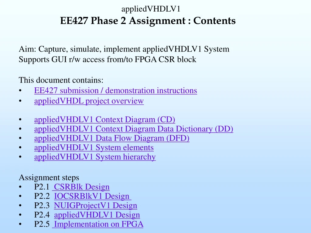
EE427 Phase 2 Assignment : Contents • Aim: Capture, simulate, implement appliedVHDLV1 System • Supports GUI r/w access from/to FPGA CSR block • This document contains: • EE427 submission / demonstration instructions • appliedVHDL project overview • appliedVHDLV1 Context Diagram (CD) • appliedVHDLV1 Context Diagram Data Dictionary (DD) • appliedVHDLV1 Data Flow Diagram (DFD) • appliedVHDLV1 System elements • appliedVHDLV1 System hierarchy • Assignment steps • P2.1 CSRBlk Design • P2.2 IOCSRBlkV1 Design • P2.3 NUIGProjectV1 Design • P2.4 appliedVHDLV1 Design • P2.5 Implementation on FPGA
Context Diagram Aim: Capture, simulate, implement appliedVHDLV1 System Supports GUI r/w access from/to FPGA CSR block
Context Diagram Data Dictionary • clk : system strobe (50MHz oscillator) • rst : asynchronous system reset (high asserted). Clears (or sets) registers • RxD : serial port data received by appliedVHDL system from host • TxD : serial port data transmitted to host by appliedVHDL system • seg7L(6:0), dpL : 7-segment display data signals. Assertion (low) lights LEDS on the Digilent Spartan-3 hardware development system • anL(3:0) : anode control signals (asserted low), e.g., upper 7-seg display segment 0 will light when anL(3)=’0’ and seg7L(0)=’0’ • ld(7:0) : 8 leds. Assertion (H) lights leds
Data Flow Diagram (DFD 0.0) Supports CSR r/w access NUIGProjectV1 DFD 2.0 DFD 3.0 DFD 1.1 V1
System Elements Project Element Activity (ref glossary) IOCSRBlkV1 contains CSRBlk: Control and Status Register (CSR) block C, S, I IOCtrlrV1: I/O controller Finite State Machine (FSM, Parses host GUI commands and data from UART), register command C, FSM, S, I datCtrlrV1 Simply connects CSROut(7:0) to txDat(7:0) C, S, IRefer to DFD 0.0 appliedVHDLV1(top level): C, S, I NUIGProjectV1: contains IOCSRBlkV1 and datCtrlrV1UART Xilinx UART component ProvideddisplayCtrlr: Multiplexed 7-segment display and LED controller Completed (phase 1) Glossary : FSM : Finite State Machine C : VHDL CaptureS : Simulation I : ImplementationBFM: VHDL Bus Functional Model
System Hierarchy Use the active links to browse the design hierarchy and documentation ISE Project : appliedVHDLV1.ise (provides access to all of constituent files) P2.4 CD, DFD1.0 V1 P1.2 NUIGPackage cascadedBCDCntrAndDisplay P2.3 P1.1 / P2.4 P2.4 DFD3.0 DFD1.0 V1 DFD2.0 P2.2 DFD1.1 V1 P2.3 P2.1 DFD1.1.2
DFD 0.0 Incremental Data Dictionary • rxDat(7:0) : byte-wide data generated by UART from serial byte received from host. rxDat is validated by assertion (h) of rxDatValid • rxDatValid :assertion (h) validates rxDat(7:0). Signal remains asserted until assertion of rxDatAck • rxDatAck : assertion by FPGA acknowledges receipt of a valid rxDat byte. Signal asserts for one clock period only • txDat(7:0) : byte-wide data generated by FPGA and transferred to UART for serialisation and transfer to host PC. txDat is validated by assertion (h) of txDatValid • txDatValid : assertion (h) validates txDat(7:0)
Assignment instructions continued P2. 1 CSRBlk • Capture, simulate and synthesise the CSRBlk
Assignment instructions continued P2. 2 IOCSRBlkV1 level • Review/verify/complete IOCSRBlkV1.vhd • Decodes UART control/data byte sequence. Handshakes with host via UART byte interface CSR access : provides Control and Status Register (CSR) R/W access (8 byte-wide CSRs) • Includes IOCtrlr FSM process(es), CSRBlk component instance and cmdReg process. • Check VHDL code syntax, synthesise and view RTL schematic. Confirm correctness. • Simulation is not required at this level
IOCtrlrV1 FSM description Refer to course notes on VHDL Finite State Machine Description Refer to FSM flowchart • Finite State Machine (FSM) detects and processes control or data byte (rxDat) from UART (on assertion of rxDatValid signal). • Decodes : • CSR access : • Registers csrAdd(2:0) and csrTask flag • write : requires a further data byte (on rxDat) from UART • read : provides CSR data byte (csrOut) to UART on txDat • Validates byte data transmission to UART (txDatValid assertion) • Acknowledges receipt of byte data (rxDat) from UART (rxDatAck assertion)
Assignment instructions continued P2.3 NUIGProjectV1 level • Review/verify/complete NUIGProjectV1.vhd. • Includes IOCSRBlkV1 and datCtrlrV1 elements (VHDL code is provided) • Check VHDL code syntax, synthesise and view RTL schematic. Confirm correctness. • Review the NUIGProjectV1_TB.vhd VHDL testbench code and modelsim macro files • Simulate NUIGProjectV1_TB.vhd fully, review the timing waveform and verify correct VHDL model operation. P2. 4 appliedVHDLV1 level • Review/verify/complete appliedVHDLV1.vhd. Includes NUIGProjectV1, UART and displayCtrlr components (VHDL code is provided) • Check VHDL code syntax, synthesise and view RTL schematic. Confirm correctness. • Review the appliedVHDLV1_TB.vhd VHDL testbench code and modelsim macro files • Simulate appliedVHDLV1_TB.vhd fully, review the timing waveform and verify correct VHDL model operation P2.5 Implement on FPGA • Review appliedVHDLV1.ucf (provided) for pinout • Implement appliedVHDLV1 on the Spartan 3 development system and test