Download
1 / 38
380 likes | 397 Views
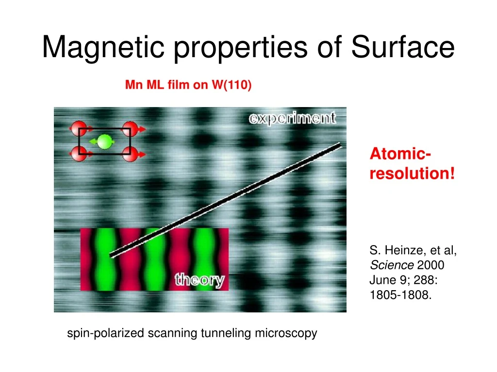
Magnetic properties of Surface. Mn ML film on W(110). Atomic- resolution!. S. Heinze, et al, Science 2000 June 9; 288: 1805-1808. spin-polarized scanning tunneling microscopy. Magnetic materials. ferromagnetic materials: Elements: Fe, Ni, Co, and their alloys

E N D
Magnetic properties of Surface Mn ML film on W(110) Atomic- resolution! S. Heinze, et al, Science 2000 June 9; 288: 1805-1808. spin-polarized scanning tunneling microscopy
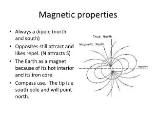
Magnetic materials • ferromagnetic materials: • Elements: Fe, Ni, Co, and their alloys • Oxides: Ferrite, Ni-Zn Ferrite • some ionic crystals: CrBr3, EuI (anti-ferromagnetic materials, etc…, what are the definitions?) magnetism is based on quantum mechanical exchange interaction!
Hysteresis curve Quantities: Ms = saturation magnetization Hc = coercive field µ = (initial) permeability - hard magnetic materials Hc > 300 Oe - soft magnetic materials Hc < 0.05 Oe
Magnetic Energies • Exchange energy alignement of spins, cost of energy to change direction of magnetization compensated by thermal energy Þ phase transition at Tc • magnetostatic energy discontinuity of normal component across interface Þ demagnetizing factor f(shape of sample) • magnetocrystalline anisotropy preference of magnetization along crystallographic directions • magnetoelastic energy Change of magnetization due to strain (magnetostriction) • Zeeman energy potential energy of magnetic moment in a field
Domain Wall Energy Energetic considerations: domain wall costs wall energy, but reduces magnetostatic energy More Domains = smaller spacing d Magnetostatic energy density Domain wall energy density ¯ Competition Þ minimization of energy Types of domain Walls a) Bloch b) Neel c) cross-tie (c)
Influence of reduced dimension Þ (surface and interface) • Real dimensionality effect. transition? • Influence from surface and interface (symmetry breaks) There is transition and effects are gradual: reduced neigbors Þ reduced overlap Þ smaller dispersion of electron bands Þ higher electron density Þ different electrons number for spin up and spin down Þ different magnetic moment.
3 dimensional case: Density of states (DOS) from free electron theory K space The density of states as function of k: sphere Density of the states:
2 dimensional case: K space The density of states as function of k: dk N(E) E dk 1 dimensional case: The density of states as function of k:
Stoner Model for Band Ferromagnetism Spin-dependent exchange coupling > different electron density of states (N+ and N-) Majority Minority For different spin electron, potential
Stoner Model for Band Ferromagnetism The three solutions for To be magnetic, require High exchange coupling High DOS at EF In the bulk Fe, Co, and Ni satisfies the requirement. While on the surface, the band width is different and so the density of states at fermi surface is also changed, it causes the magnetic moment different from the bulk, while Cr and Mn can be magnetic at the surface.
(For Ising model, ) Molecular theory (Weiss, 1907) with approximation, Average field (molecular field) where, with
For third order approximation, With , two solutions: When H=0 and H S
1-d Ising model Chain of N spin, spins only +1 or -1 Only interact with the next neighbor 1 2 3 N-1 N Study two spin correltion <SkSl> replace SkSk+1 with Sk,K+1 For large system and l-k is large number, No long range order at finite T!
2d-Ising and 3d-Ising and more Landau 2d-Ising 3d-Ising 3d-XY 3d-Heisenberg ½ 1/8 ~0.325 ~0.3454 ~0.3646 1 7/4 ~1.24 ~1.316 ~1.3866 3 15 ~4.816 ~4.81 ~4.803 Theory on 3-d models are all numeric. It was proven that no ferromagnetism at finite T in less than 3 dimensions in a spin system with a certain isotropy. Magnetism in reduced dimensions stabilized by anisotropy. 0.8MLFe/W(110) β ~ 0.124 γ ~ 1.75 Ni/W(110)
Thickness of Tc on film thickness Assume ferromagnetism only if d<t, it understandable there will be thickness dependence of Tc on film thickness. Co/Cu(001) ν~0.71 Ni/W(110) Islands contributions
Volume vs. interface anisotropySpin-reorientation transition (SRT) Phenomenological separation of anisotropy into “volume” and “interface” Generally, Volume (including shape) contribution tends to make spin in-plane. When K1s<0, there will be SRT from out-of-plane to in-plane SRT. Ni/Cu(001) Unusual SRT due to the contribution from magnetoelastic anisotropy.
Exchange coupling RKKY Model for 3d free electrons gives: Scanning Electron Microscopy with Polarization Analysis (SEMPA) from Fe/Cr/Fe Period is
More sophisticated theory and exp. Period determined by Fermi surface: “spanning vectors” in direction of the film normal gives oscillation period: K1 For Cu(001): K2 Ǻ Ǻ For Au(100) Ǻ Ǻ Fe/Au/Fe Overlap of two periods
Magnetic Quantum Well Statesthe origin of exchange coupling When ferromagnetic layer contacts diamagnetic layer, for majority spin electrons at EF in FM are s electrons like in the diamagnetic layer, while minority electrons at EF are mainly d electrons, which have different from in the diamagnetic layer (s). s electrons with minority characterin diamagnetic layer are confines and cause quantum well states with spin dependence. In diamagnetic layer between two FM layers, DOS changes while the thickness of diamagnetic layer changes, to lower the total energy Only Minority has strong effect Different alignment of the two FM layers at different diamagnetic layer thickness Exchange coupling !
Giant magnetoresistance (GMR) Simple model In ferromagnetic material:
Spin Valves One layer free One pinned Notice the bias hard magnetic underlayer “pins“ soft magnetic top layer resisitivity changes abrupt for flip of magnetization
Toward Spintronics Spin-valve transistor PLD to make spintronics Science 291: 840-841(2001)
VSM (Vibrating Sample Magnetometer) According to Faradays laws of magnetic induction, an ac voltage is induced in the electrical which is proportional to the rate of change of magnetic flux linking the circuit, and therefore to the size of the moment within the sample due to the applied magnetic field. As the sample is vibrated in the vertical direction near the detection coil, an ac signal is generated at a frequency determined by the sample oscillation. Most common technique that is employed for hysteresis loop measurements. Various materials. Bulk.
MOKE (Mangeitc optical Kerr effect) Polar Longitudinal Transverse roatation of polarization plane of polarized light due to sample magnetization depends on direction of magnetization. Very sensitive and stable, but lack the surface sensitivity, can be used as magnetic microscopy signal source and hysteresis loop measurements
SEMPA(Scanning Electron Microscopy with Polarization Analysis) SEMPA images the magnetization by measuring the spin polarization of secondary electrons emitted in a scanning electron microscope. The secondary electron spin polarization is directly related to the magnetization of the sample. SEMPA therefore produces a direct image of the magnitude and the direction of the magnetization in the region probed by the incident electron beam. First layer Second layer (remove first) measure magnitude and direction of the magnetization. high spatial resolution (about 10 nm), long working distance, large depth of field characteristic of SEM. independent from topography but with topography. surface sensitive technique(~1 nm) Antiparallel Magnetic Order in Weakly Coupled Co/Cu Multilayers (J. A. Borchers,et al., PHYSICAL REVIEW LETTERS, 48 (1999) 2796
SQUID (superconductingquantuminterference devices) SQUID is loop of superconductor that contains one or more Josephson Junctions. (interface between two superconducting materials separated by a non-superconducting barrier. A current may flow freely within the superconductors, but the barrier prevents the current from flowing freely between them. However, the supercurrent may tunnel through the barrier, depending on the quantum phase of the superconductors. The amount of supercurrent that may tunnel through the barrier is restricted by the size and substance of the barrier. The maximum value the supercurrent may attain is called the critical current of the Josephson junction, and is an important phenomenological parameter of a junction). Parallel Josephson junctions made by photolithography. When bias current (Ib) is applied to the SQUID, voltage through the SQUID is zero if the current is less than critical current. When bias current exceeds critical current (Ic), the SQUID turns to the normal state and voltage is produced.
SQUID Magnetic field measure A SQUID sensor with 0.5 mm wide step-edge Josephson junctions. When a flux is introduced into the SQUID loop, the critical current decreases. When the bias current is fixed at a slightly higher value than the critical current and an external magnetic field is applied, the voltage will change in a periodic wave in accordance with the flux quantization. We can measure the magnetic field by monitoring the change in voltage.
AC-Susceptibility measurement With IDc to change the magnetic field and Ac current to modulate it, the pick up coil will detect the ac susceptibility. integrate
XMCD (synchrotron related) From the selection rules, the IL3 and IL2 are proportional to d holes, while the spin and orbital moment can be calculated from the difference A and B (dichroism).(Sum rule) Element-specific, quantitative. Can be used as signal for electron microscopy. With good design, magnetic loop can also be measured. It is also element-resolved!
XMLD (synchrotron related) Only sensitive to spin along which axis XMLD can study the AFM ordering, by combining XMCD more magnetic information can be obtained.
Spin-polarized photoemission Spin-resolved photoemission is powerful tool to study spin-resolved electronic structure (for example band mapping for valence band), which can compare directly with theory. PRB. 51, (1995) 12627
Spin detectors Spin detector is the essential part for spin-resolved experiments. Mott detector: The Micro-Mott polarimeter utilises Mott scattering of electrons from a target foil (big Z, normally Au) that is maintained at a potential of 20kV. The scattered electrons are then decelerated to close to ground potential for detection by channel plates. There are four detectors, each placed at angle of 120° to the incident electron beam, and equispaced in azimuth, so as to detect back-scattered electrons. These are used to measure the two transverse components of the beam polarisation. SPLEED detector: based on spin-polarized low energy electron diffraction (SPLEED) from big Z target (W(110)). It uses low voltages (scattering energy is 104 eV) and features a very high asymmetry function of > 0.2. Four integrated channeltrons allow simultaneous measurement of transversal spin vector components. Its total scattering intensity is concentrated into a few well-defined diffraction spots.
Spin detectors SPLEED Mott detector Scattering is generally low efficient, which means tedious and time consuming: sometime alternative photoemission dichroism can offer similar information.
Magnetic dichroism in angular-resolved photoemission (MDAD) No sum rule yet! 2p levels as example By reversing magnetization or helicity of the light, there will be different photoemission spectrum (dichroism) when M have a component along the direction of the light. (MCDAD) With linear or un-polarized light, M reversing along normal of the plane consisting of q and k, there will be also MLDAD. Symmetry break….
MDAD Notice the reversed sign for the two 2p Levels.
Hall effect If an electric current flows through a conductor in a magnetic field, the magnetic field exerts a transverse force on the moving charge carriers which tends to push them to one side of the conductor. This is most evident in a thin flat conductor as illustrated. A buildup of charge at the sides of the conductors will balance this magnetic influence, producing a measurable voltage between the two sides of the conductor. n density of mobile charge density, e elctron charge. The Hall effect can be used to measure magnetic fields with a Hall probe. Can be used for scanning microscope, with resoltuion of mm. (SQUID probe….)
Spin-resolved STM Basically use magnetic or anti-ferromagnetic tip to have spin dependent tunneling: One kind separate the spin-dependent part of the tunnel current by rapidly changing the magnetization of the tip in combination with a lock-in detection of the variations in the tunnel current. STM images of the topography (a) the magnetic domain structure of the same area (b) of Co(0001). Sample bias: 0.2 V; tunneling current: 0.5 nA; (a) height variations 4 nm; (b) spin contrast: 3.6%. S. Heinze, et al, Science 2000 June 9; 288: 1805-1808. Even Atomic scale Hysteresis (Science 2001, June 15:292:2053-2056) Appl. Phys. Lett. 75, 1944, (1999)