Download
1 / 33
330 likes | 335 Views
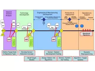
Chapter 14. System Testing. System Testing. “ Intuitively clear ” customer expectations close to customer acceptance testing BUT we need a better basis for really understanding system testing Threads—the subject of system testing How are they identified? ad hoc? from experience?

E N D
Chapter 14 System Testing
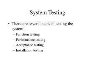
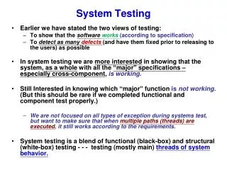
System Testing • “Intuitively clear” • customer expectations • close to customer acceptance testing • BUT we need a better basis for really understanding system testing • Threads—the subject of system testing • How are they identified? • ad hoc? • from experience? • from a possibly incomplete requirements specification? • from an executable model? (Model-Based Testing)
Threads... • (not nice clothes...) • An execution time concept • Per the definition, a thread can be understood as a sequence of atomic system functions. • When a system test case executes • a thread occurs, and • can be observed at the port boundary of the system • The BIG Question: where do we find (or how do we identify) threads? • Our approach—Model-Based Testing
Threads—Several Views • A scenario of normal usage • A use case • A stimulus/response pair • Behavior that results from a sequence of system-level inputs • An interleaved sequence of port input and output events • A sequence of transitions in a state machine description of the system • An interleaved sequence of object messages and method executions • A sequence of machine instructions • A sequence of source instructions • A sequence of MM-paths • A sequence of atomic system functions (to be defined)
Some Choices—Threads in an ATM System • Entry of a digit • Entry of a personal identification number (PIN) • A simple transaction: ATM Card Entry, PIN Entry, select transaction type (deposit, withdraw), present account details (checking or savings, amount), conduct the operation, and report the results • An ATM session containing two or more simple transactions • Each of these can be understood as an interleaved sequence of port level inputs and outputs.
Details of PIN Entry as a Thread • A screen requesting PIN digits. • An interleaved sequence of digit keystrokes and screen responses. • The possibility of cancellation by the customer before the full PIN is entered. • A system disposition: • A customer has three chances to enter the correct PIN. • Once a correct PIN has been entered, the user sees a screen requesting the transaction type. • After three failed PIN Entry attempts, a screen advises the customer that the ATM card will not be returned, and no access to ATM functions is provided.
Definition: Atomic System Function • Definition: An Atomic System Function (ASF) is an action that is observable at the system level in terms of port input and output events. • About ASFs • characterized by a sequence of port level inputs and outputs • could be just a simple stimulus/response pair (e.g. digit entry) • Sample ASFs in our ATM example • card entry • PIN entry • Transaction selection • session termination
More Definitions… • Given a system defined in terms of atomic system functions, the ASF Graph of the system is the directed graph in which nodes are ASFs and edges represent sequential flow. • A source ASF is an Atomic System Function that appears as a source node in the ASF graph of a system. • A sink ASF is an Atomic System Function that appears as a sink node in the ASF graph. • A system thread is a path from a source ASF to a sink ASF in the ASF graph of a system.
Basis Concepts for Requirements Specification • All of requirements specification models are developed on these basis concepts. • Data • Inputs to actions • Outputs of actions • Events • Inputs to actions • Outputs of actions • Actions • Threads (sequences of actions) • Devices
Paths in the SATM PIN Try State Correct PIN on first try state sequence <S2.n.0, S2.n.1, S2.n.2, S2.n.3, S2.n.4, S3> Port Event Sequence 1st digit, echo “- - - *” 2nd digit, echo “- - * *” 3rd digit, echo “- * * *” 4th digit, echo “* * * *” Enter Failed PIN on first try state Sequences <S2.n.0, S2.n.6> <S2.n.0, S2.n.1, S2.n.6> <S2.n.0, S2.n.1, S2.n.2, S2.n.6> <S2.n.0, S2.n.1, S2.n.2, S2.n.3, S2.n.6> <S2.n.0, S2.n.1, S2.n.2, S2.n.3, S2.n.4, S2.n.6>
How Many Paths in the PIN Try State? • 1st try: 1 correct + 5 failed attempts • 2nd try: 5 failed 1st attempts * 6 second attempts • 3rd try: 25 failed 1st and 2nd attempts * six third attempts • Do we really want to test all of these? • This foreshadows the question of “long” versus “short” use cases.
Automated Test Case Execution Basic architecture: Use cases interpretively executed CAUSE inputs VERIFY outputs Check observed versus expected outputs via a harness connected to the System Under Test
Executable Test Case for Correct PIN on First Try Set up requirements: Screen 2 is displayed CAUSE TouchDigit(2) VERIFY Screen 2 shows ‘---*’ CAUSE TouchDigit(4) VERIFY Screen 2 shows ‘--**’ CAUSE TouchDigit(6) VERIFY Screen 2 shows ‘-***’ CAUSE TouchDigit(8) VERIFY Screen 2 shows ‘****’ VERIFY Screen 5 is displayed
Long versus Short Use Cases A “Long” use case is typically an end-to-end transaction. SATM example: A full traversal of the high level finite state machine, from the Welcome screen to the End Session screen: <s1, s2, s3, s4, s5> A “Short” use case is at the level on an atomic system function. Examples PIN Entry Transaction selection Session closing
Short Use Cases • A “Short” use case is at the level on an atomic system function (ASF). • In the directed graph of ASFs, • nodes are ASFs • edges signify possible sequential execution of ASFs • Consider an ASF as a “Short” use case, with • pre-conditions • post-conditions • Short use case (ASF) B can follow short use case (ASF) A if the pre-conditions of B are consistent with the post-conditions of A, that is... • Short use cases “connect” at their pre- and post condition boundaries.
How Many Use Cases? • 1909 “long” use cases • 25 “short” use cases • Ways to determine “how many? • Incidence with input events (cover every input event) • Incidence with output events (cover every output event) • Incidence with classes (need a use case/class incidence matrix) • These lead directly to system testing coverage metrics.
System Testing with Short Use Cases • Basic idea: a short use case is an atomic system function (ASF) • ASFs ... • begin with a port input event • end is one of possibly several port output events • ASFs can be identified • in source code • in executable models • from short use cases • Example: the integration version of NextDate • (see text)
Using Operational Profile when interested in“Effectiveness” • The effectiveness of testing is often measured in terms of problems found versus effort spent or • (# of defects found) / person hours spent • (# of defects found) / number of test cases • Historically, most of the failures also tend to fall in small parts of the system (80% failures occur in 20% of the system - - - e.g. the most heavily traversed threads). • Thus if we can collect the operational profilesof the users, we can identify the most heavily used threads. • Thisstrategy of system testing with operational profile can improve our test efficiency. Not just the number of problems found
User-Operational Profile Example(naïve user versus experienced user) (20/20) (20/20) prob = .25 √ term naïve users (20/80) default f1 f4 (5/5) prob = .063 (5/10) f4 term Start (80 users) (5/10) (5/5) prob = .063 (10/60) f1 f6 term experienced users (60/80) (40/40) (40/40) (40/60) prob = .50√√ term f7 f2 Choice of f1,f2,f3 (10/60) (3/10) (3/3) prob = .037 term f4 f3 (7/10) (7/7) prob = .087 f5 Note that 2 usage cases take up 75% of operational profile ! term