Download
1 / 21
210 likes | 379 Views
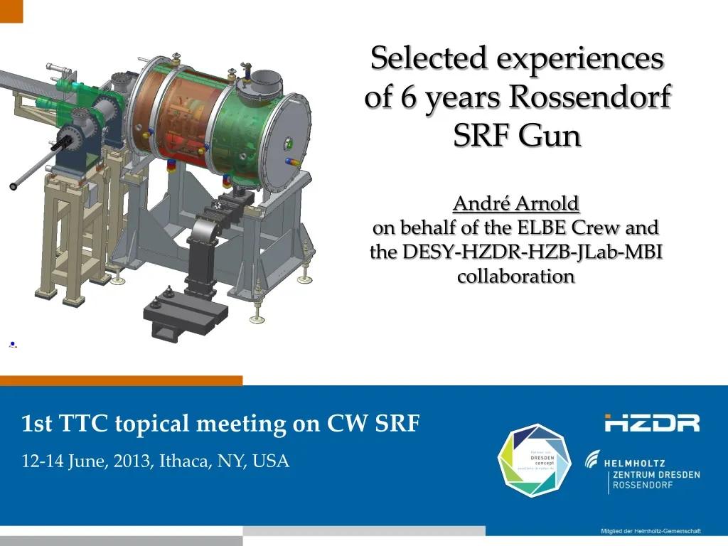
Selected experiences of 6 years Rossendorf SRF Gun. André Arnold on behalf of the ELBE Crew and the DESY-HZDR-HZB-JLab-MBI collaboration. 1st TTC topical meeting on CW SRF 12-14 June, 2013, Ithaca, NY, USA. Outline. Introduction CW operation Mech. properties Intrinsic quality factor

E N D
Selected experiences of 6 years Rossendorf SRF Gun André Arnold on behalf of the ELBE Crew and the DESY-HZDR-HZB-JLab-MBI collaboration 1st TTC topical meeting on CW SRF 12-14 June, 2013, Ithaca, NY, USA
Outline • Introduction • CW operation • Mech. properties • Intrinsic quality factor • HOM coupler • Cathode • Preparation • Multipacting • Dark current • New Cavity • Summary
Introduction – SRF gun designed for ELBE • Three CW operation modes • high peak current operation for CW-IR-FELs with 13 MHz, 80 pC • high bunch charge (1 nC), low rep-rate (<1 MHz) for pulsed secondary particle beam production (neutrons, positrons for ToF) • low emittance (1 mm mrad), medium charge (100 pC) with short pulses for THz-radiation and x-rays by inverse Compton backscattering Laser 1 W, 262 nm Choke Filter HOM Coupler 3 TESLA Cells • Bpeak= 110 mT • Epeak = 50 MV/m • U = 33 J • Vacc = 9.4 MV • G = 241.9 Ω • R/Q = 166.6 Ω • Q0 = 1010 • Pdiss = 26 W Electron Beam 10 MeV, 1 mA, 10 kW 77 pC - 1 nC Cathode Half Cell Main Coupler
connected to all peripherals and diagnostics Screen 1 Screen 2 & slit masks Cherenkov radiator Faraday cup 180° magnet Solenoid e--beam Length = 4m Laser beam developed & manufactured by HZB Introduction – SRF gun in 2007 From in-house clean room cavity string assembly to SRF gun module completion SRF gun in the acc. tunnel
125Hz (1st mech. resonance) 24Hz (membrane pumps) 10Hz (LHe compressors) 1. CW Operation – mech. Properties • Pressure sensitivity TESLA 9 cell: ~10 Hz/mbar Reason is the weak half-cell back plane → additional stiffeners welded at new cavities • Lorentz detuning using NWA in CW TESLA 9 cell: ~0.25 Hz/(MV/m)2 kpeak = 0.69 Hz/(MV/m)2 • Microphonics using LLRF controller time signals
1. CW Operation – In Situ Q0 vs. Epk @ 2K Q vs. E measurement is an important instrument to identify cavity contamination! • Formulas: • Good News • No Q degradation during the first 4 years of operation! • Small improvement after HPP (but canceled by thermal cycle) • Bad News • measured Q0 is 10 times lower than in vertical test • Maximum achievable field 1/3 of the design value 50 MV/m) • Cavity performance limited by FE & He consumption (>30 W) • performance loss 1 ½ years ago, due to cathode exchanges ? Q0 degradation possibly due to cathode exchanges Summary:
beampipe HOM1 HOM2 Epk=15 MV/m ∆1K 1. CW Operation – HOM hook coupler • Ti:sapphire HOM feed through • RF cable with coppered stainless steel inner conductor (same as DESY) • No significant temp. increase in CW (∆1K) (no significant HOM power @ 13 MHz, 30 pC) • Interesting possibility of hook couplers: • R/Q calculation from energy loss per bunch, if mode damping caused by HOM couplers • Measurement with spectrum analyzer (zero span) rhodium iron temp. sensor
2. Cathode – Preparation and Operation • Cathodes evaporated with Cs and Te (succes-sively or simultaneously) until QE is saturated • Immediately after preparation QE drops fast to about 1% and remains const. also in the gun • Up today: 9 Cs2Te cathodes used in the gun • Most of them died because of vacuum problems fresh QE 8.5%, in gun 0.6% total beam time ~600 h extracted charge 260 C max beam current 400µA
2. Cathode – Multipacting • MP was expected since the early days of the cavity design! • And indeed it appeared at low field (<1 MV/m) for every Cs2Te cathode • Characterized by high current (>1 mA, rectified) at the cathode and electron flash at view screens • Biasing of the electrically isolated cathode up to -7 kV usually works (voltage is different for every cathode and position!) • Anti multipacting grooves to suppress resonant conditions and coating with TiN to reduce secondary electron yield doesn’t work for Cs2Te coated cathodes because of too high SEV due to Cs pollution? German BMBF project granted to further investigate MP and find solutions
2.0 Angle (mrad) -1.7 phase space photo beam 1pC n,rms=1.3 2.0 Angle (mrad) -2.0 phase space dark current n,rms=2.4 -3.1 position (mm) 3.0 -1.6 position (mm) 2.0 screen intensity (a.u.) DC 6 kV 16.2 MV/m 100 keV 100 keV dark current (120 nA) 30 pC photo beam 2. Cathode – Dark Current Properties • Dark current = accelerated electrons produced by FE with wrong properties in space & time • Comparison of dark current with low-bunch-charge photo beam: • Slit mask emittance measurement: dark current has similar transverse beam properties • 180° bending magnet: large fraction has nearly same energy and energy spread ( emission near or from the cathode)
2. Cathode – Dark Current Origin • whole energy spectra with and w/o cathode(intensity normalized to total current cathode curve) • High energy part belongs to cathode itself • Fractions with lower energy belongs to the cathodehole in the half cell or to other high-field regions • Total dark current for different cathodes • only cathodes with Cs2Te layer have dark current • 20 % dark current from cathode, 80% from cavity ~20%
2. Cathode – Dark Current Extrapolation • New cavity can operate at 16 MV/m. Here we expect lower field enhancement factor β, that results in the same dark current as for the old cavity but now at 16 MV/m (blue curve) • But extrapolation of FN fit for 20 % dark current emitted from cathode (ϕ = 3.5 eV for Cs2Te,) results in 40 µA cathode dark current By far too much for CW accelerators Need for cathodes with low dark current [J. Teichert, FLS2012] But how? • proper handling to prevent dust particles and surface damage • proper materials for plugs with smooth surface • photo layer properties • - roughness, homogeneity, thickness • - work function • - crystal size, boundary and structure • - post-preparation treatment (protect layer, heating, …) • - pre-conditioning Further investigations within German Gun-Cluster collaboration and ARD
additional half-cell stiffening (light green) modified choke-cell pick-up flange larger cathode boring 3. New SRF Gun – The stony path to a new cavity RRR 300 Nb cavity large grain Nb cavity • Main aim: approach the design value of Epk=50 MV/m: • Fabrication of two new cavities in collaboration with JLab (fabrication, treatment, test by P. Kneisel and co-workers) • Slightly modification compared to old design to: • Lower Lorentz force detuning, microphonics and pressure sensitivity • Improve cleaning and simplify clean room assembly
3. New SRF Gun – The stony path to a new cavity My suggestion for future projects - Keep it simple and straightforward (KISS) corresponding to a beam energy of 8 MeV existing SRF gun
Summary • Pressure sensitivity and Lorentz force detuning higher than for TESLA cavities • High microphonics but residual phase noise (closed RF loop) still sufficient in all three cases stiffeners for the weak half cell needed • No Q degradation of Cavity during first 4 years but then Q-drop due to cathodes? NC cathodes and its exchange are a potential risk forSRF guncavities • No heating of Ti:sapphire HOM feed through in CW operation at Epk = 15 MV/m • Longlifetime of NC photo cathodes in SRF gun (>1 yr, total charge 260 C @ QE 1% ) • Multipacting appears for Cs2Te coated cathodes only, suppression with DC Bias • Cs2Te cathodes produces high dark current with similar properties as the photo beam, for higher surface fields 40 µA are expected, which is a problem for CW accelerators • RRR300 upgrade cavity (+vessel) tested up to 43 MV/m, cold mass assembly upcoming
Summary - First FEL Operation with the SRF gun ELBE infrared FEL (20 – 250 µm) before first lasing optimized April 11, 2013 NIM paper submitted stabilty FEL spectra FEL detuning curve
Thanks to our collaborators (HZB for diagnostics, MBI for the laser and DESY for preparation and testing of the 1st cavity) and thank you for your attention! ELBE Crew in front of museum of clocks in Glashütte, Germany Acknowledgement We acknowledge the support of the European Community-Research Infrastructure Activity under the FP6 programme 2004-08 (CARE, contract number RII3-CT-2003-506395) and the FP7 programme since 2009 (EuCARD, contract number 227579) as well as the support of the German Federal Ministry of Education and Research grant 05 ES4BR1/8.
Introduction – 3D Cross-section of the Module • LHe supply • Ti spokes for cavity alignment and thermal decoupling • LN tank for cryo shielding • Mu metal shielding • Cathode with LN heat sink • LN tank for cathode and tuning system • LHe vessel with sc 3.5 cell gun cavity • RF coupler (10 kW) • Dual tuner 2 1 4 3 9 7 5 6 8 isolation vacuum Quelle: A. Arnold, et al., NIM A 577, 440 (2007)
CW Operation – Cavity Dual Tuner stepping motor and gear box screw drive measured tuner values
Dark current measurement and analysis Dark current energy spectrum with cathode #170412Mo Measured with dogleg dipole + YAG screen, normalized according to the total dark current measured from Faraday cup. DC 6kV Different energy different position? Simulation needed.
DARK CURRENT – Fowler Nordheim analysis Fowler Nordheim formula for field emission current: Fowler Nordheim plot for RF fields: E: surface field amplitude in V/m, ɸ: work function in eV, β: field enhancement factor. (J.W. Wang and G.A. Loew, SLAC-PUB-7684 October 1997) F-N plots for the SRF gun caivty фNb = 4.3 eV β ≈ 400 Sharp emitter