Download
1 / 55
550 likes | 642 Views
MARIE Instruction Set Architecture. A computer ’ s instruction set architecture (ISA) specifies the format of its instructions and the primitive operations that the machine can perform. The ISA is an interface between a computer ’ s hardware and its software.

E N D
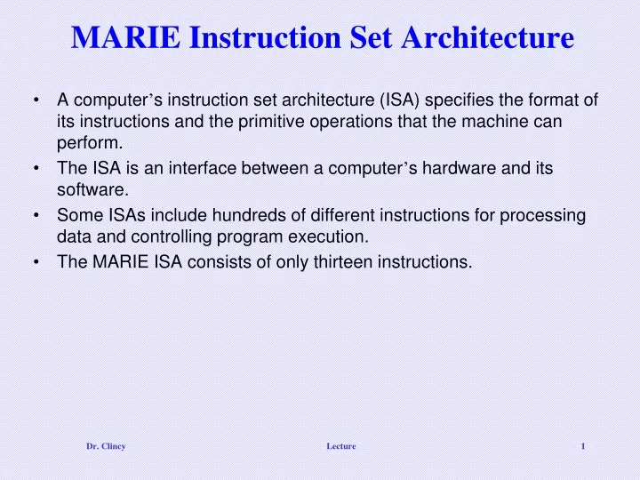
MARIE Instruction Set Architecture • A computer’s instruction set architecture (ISA) specifies the format of its instructions and the primitive operations that the machine can perform. • The ISA is an interface between a computer’s hardware and its software. • Some ISAs include hundreds of different instructions for processing data and controlling program execution. • The MARIE ISA consists of only thirteen instructions. Lecture
MARIE ISA • This is the format of a MARIE instruction: • The fundamental MARIE instructions are: • Specifies the instruction to be executed, therefore 24=16 instructions • Allows for a maximum size of memory of 212 - 1 Lecture
LOAD Instruction • The Load instruction allows data to be moved from memory into the CPU via the MBR and the AC • All data must be first moved into the MBR and then either into the AC or ALU • The Load instruction doesn’t have to name the AC as a final destination, the AC register is implicit in the instruction • This is a bit pattern for a LOAD instruction as it would appear in the IR: • We see that the opcode is 1 and the address from which to load the data is 3. Lecture
Intro to Other Instructions • Allows data to be moved from the CPU back to memory • Typically represented as ASCII. In real-life, has to be converted if used as numeric. For MARIE, assume numeric only • Causes the current program execution to terminate • Move the data value found at address X into the MBR, then add the MBR value to the value in the AC • Move the data value found at address X into the MBR, then subtract the MBR value from the value in the AC • Allows conditional branching (ie. while loops, if statements). When the instruction is executed, the value in the AC is inspected • Allows an unconditional branch. When the instruction is executed, it causes the contents of the Program Counter (PC) to be replaced with the value of X, which is the address of the next instruction to fetch – thus skipping Lecture
SKIPCOND Instruction • As mentioned earlier, when SKIPCOND is executed, the value in the AC is examine • In MARIE’s case, address bits 10 and 11 are examined: • Bits used to specify the condition to be tested • If 00, translates to “bypass the next instruction if the AC is negative” • If 01, translates to “bypass the next instruction if the AC is equal to 0” • If 10, translates to “bypass the next instruction if the AC is greater than 0” • If 11, an error condition occurred • This is a bit pattern for a SKIPCOND instruction as it would appear in the IR: • We see that the opcode is 8 and bits 11 and 10 are 10, meaning that the next instruction will be skipped if the value in the AC is greater than zero. Lecture
Examine Some Instructions • Opcode is binary 1, for LOAD. The address where the value in located in memory is 3. Data found at address 3 is copied into the AC • Opcode is binary 3, for ADD. The address where the value in located in memory is 13. Data found at address 13 is placed in the MBR, then the MBR value is added to the value in the AC, and then the value in the AC is over-written with the sum • Opcode is binary 8, for SKIPCOND. Bits 11 and 10 are 10 indicating bypass the next instruction if the AC is greater than 0. If the AC’s value is less than or equal to zero, this instruction is ignored and the next instruction is executed. Otherwise, the PC is incremented by 1, thus skipping Lecture
MARIE Register Transfer Notation • Instead of using binary values to represent the instruction, instruction names or mnemonics used (pronounced Nee-Monics) • Binary version – called machine instructions • Mnemonics version – called assembly language instructions • An assembler’s job is to convert the assembly instructions into the machine instructions • Recall that architectures are comprised of various components like the ALU, registers, memory decoders and control units • A single machine instruction causes these components to execute tasks • Each machine instruction can consist of multiple component-level operations • Mini-instructions are being executed. These mini-instructions are called microoperations • The exact sequence of microoperations that are carried out by an instruction can be specified using register transfer language (RTL) or register transfer notation (RTN). • In the MARIE RTL, we use the notation M[X] to indicate the actual data value stored in memory location X, and to indicate the transfer of bytes to a register or memory location. Lecture
MARIE LOAD RTL • The RTL for the LOADinstruction is: • Loads the contents of memory location X into the AC. • Address X is placed into the MAR. The IR uses the bus to copy the value of X into the MAR MAR X MBR M[MAR] AC MBR • Data at location M[MAR] (or address X) is moved into the MBR. This operation and the operation above must be in sequence and can’t occur at the same time • Data is then placed in the AC. This operation can occur immediately after the above operation because the MBR and AC have a direct connection with one another Lecture
MARIE STORE RTL • The RTL for the STORE instruction is: • Stores the contents of the AC in memory location X. MAR X, MBR AC M[MAR] MBR • Address X is placed into the MAR and also the content or value in the AC is placed in the MBR • The contents of the MBR is stored at location M[MAR] (or address X) Lecture
MARIE ADD RTL • The RTL for the ADD instruction is: • Data stored at memory location X is added to the AC. MAR X MBR M[MAR] AC AC + MBR • Address X is placed into the MAR • Data at location M[MAR] (or address X) is moved into the MBR • Data in the MBR is added to the value in the AC and the result is stored back in the AC Lecture
MARIE SUB RTL • The RTL for the ADD instruction is: • Data stored at memory location X is added to the AC. MAR X MBR M[MAR] AC AC - MBR • Address X is placed into the MAR • Data at location M[MAR] (or address X) is moved into the MBR • Data in the MBR is subtracted from the value in the AC and the result is stored back in the AC Lecture
MARIE INPUT, OUTPUT, HALT RTL • INPUT AC InREG OutREG AC No Operation • Input for any input device is first placed into the InREG, then the data is transferred into the AC • OUTPUT • Contents of the AC is placed into the OutREG, and eventually sent out to an output device • HALT • No operations performed on registers – the machine simply ceases execution of the program Lecture
MARIE JUMP RTL • The RTL for the JUMP instruction is: • Causes an unconditional branch to the given address, X. PC X PC IR[11-0] • Therefore to execute this instruction, the address X, must be loaded into the PC • Since the least significant 12 bits of the 16 bits is the address, the instruction above is really Lecture
MARIE SKIPCOND RTL • Recall that SKIPCOND skips the next instruction according to the value of the AC. • Uses bits 10 and 11 to determine what comparison to perform on the AC • If the condition is true, the next instruction is skipped (PC incremented) • The RTL for the this instruction is the most complex in our instruction set: If IR[11 - 10] = 00 then If AC < 0 then PC PC + 1 else If IR[11 - 10] = 01 then If AC = 0 then PC PC + 1 else If IR[11 - 10] = 11 then If AC > 0 then PC PC + 1 • Checking if AC is negative • Checking if AC is equal to zero • Checking if AC is positive Lecture
Instruction Processing • The fetch-decode-execute cycle is the series of steps that a computer carries out when it runs a program. • We first have to fetch an instruction from memory, and place it into the IR. • Once in the IR, it is decoded to determine what needs to be done next. • If a memory value (operand) is involved in the operation, it is retrieved and placed into the MBR. • With everything in place, the instruction is executed. Lecture
Instruction Processing – Flow Chart If a memory value (operand) is involved in the operation, it is retrieved and placed into the MBR When program is first loaded, the address of the first instruction is placed into the PC Copy the contents of the PC to the MAR Go to main memory and fetch the instruction found at address in the MAR, place it in the IR, then increment the PC by 1 With everything in place, the instruction is executed. Decode the leftmost 4 bits of the IR in determining the opcode – and copy the rightmost 12 bits of the IR to the MAR Lecture
Instruction Processing - Interrupts • All computers provide a way of interrupting the fetch-decode-execute cycle. • Interrupts occur when: • A user break (e.,g., Control+C) is issued • I/O is requested by the user or a program • A critical error occurs • Interrupts can be caused by hardware or software. • Software interrupts are also called traps. • Interrupt processing involves adding another step to the fetch-decode-execute cycle as shown below Lecture
Interrupt Instruction Processing Interrupt service routines Lecture
Interrupt - Instruction Processing • For general-purpose systems, it is common to disable all interrupts during the time in which an interrupt is being processed. • Typically, this is achieved by setting a bit in the flags register. • Interrupts that are ignored in this case are called maskable. • Nonmaskable interrupts are those interrupts that must be processed in order to keep the system in a stable condition. Lecture
I/O - Instruction Processing • Interrupts are very useful in processing I/O. • However, interrupt-driven I/O is complicated, and is beyond the scope of our present discussion. • MARIE, being the simplest of simple systems, uses a modified form of programmed I/O. • All output is placed in an output register, OutREG, and the CPU polls the input register, InREG, until input is sensed, at which time the value is copied into the accumulator. Lecture
A Simple Program • Lets consider a program that adds two numbers together, storing the sum in memory • Both the assembly language program and data are stored in memory • Consider the simple MARIE program given below. We show a set of mnemonic instructions and data stored at addresses 100 - 106 (hex): • Program • Data • Result • Assembly Language • Machine Language Lecture
A Simple Program - Continuing • Let’s look at what happens inside the computer when our program runs. • This is the LOAD 104 instruction: • The PC is loaded with the address of the first instruction • The PC’s contents is stored in the MAR • The instruction at the address stored in the MAR is stored into the IR – initial instruction was fetched • PC is incremented • Address portion of the instruction is loaded into the MAR • Opcode portion is decoded • The data at the address stored in the MAR is stored into the MBR – operand 35 was fetched • The MBR’s contents is stored in the AC Lecture
A Simple Program - Continuing • The second instruction, ADD 105: • The PC’s contents is stored in the MAR (101 vs 100) • The instruction at the address stored in the MAR is stored into the IR – initial instruction was fetched • PC is incremented • Address portion of the instruction is loaded into the MAR • Opcode portion is decoded • The data at the address stored in the MAR is stored into the MBR – operand -23 was fetched • The MBR’s contents is added to the contents of the AC, and the results, 12, is stored in the AC Lecture
A Simple Program - Continued • The third instruction, STORE 106: • The PC’s contents is stored in the MAR (102 vs 101) • The instruction at the address stored in the MAR is stored into the IR – initial instruction was fetched • PC is incremented • Address where the result will be stored is loaded into the MAR • Opcode portion is decoded • No operand – this operation is not needed • The MBR’s contents is stored in main memory at the address located in the MAR • The AC’s contents is stored in the MBR Lecture
A Discussion on Assemblers • Mnemonic instructions, such as LOAD 104, are easy for humans to write and understand. Also labels can be used to identify particular memory locations. • They are impossible for computers to understand. • Assemblers translate instructions that are comprehensible to humans into the machine language that is comprehensible to computers • We note the distinction between an assembler and a compiler: In assembly language, there is a one-to-one correspondence between a mnemonic instruction and its machine code. With compilers, this is not usually the case. • Assemblers create an object program file from mnemonic source code (assembly program) in two passes. • During the first pass, the assembler assembles as much of the program as it can, while it builds a symbol tablethat contains memory references for all symbols in the program. • During the second pass, the instructions are completed using the values from the symbol table. Lecture
A Discussion on Assemblers • Consider our example program at the right. • Note that we have included two directives HEX and DEC that specify the radix of the constants. • The first pass, creates a symbol table and the partially-assembled instructions as shown (ie. doesn’t know X is located at address 104). • Also after the first pass, the translated instructions are incomplete Mnemonic instructions or alphanumeric name Label or Memory location name Lecture
A Discussion on Assemblers • After the second pass, the assembler uses the symbol table to fill in the addresses and create the corresponding machine language instructions • After the second pass, it knows X is located at address 104 and that is totally translated to machine code Lecture
Extending Our Instruction Set • So far, all of the MARIE instructions that we have discussed use a direct addressing mode. • This means that the address of the operand is explicitly stated in the instruction. • It is often useful to employ a indirect addressing, where the address of the address of the operand is given in the instruction • If you have ever used pointers in a program, you are already familiar with indirect addressing. Lecture
Extending Our Instruction Set • We have included three indirect addressing mode instructions in the MARIE instruction set. • The first two are LOADI X and STOREI X, where X specifies the address of the operand to be loaded or stored. • In RTL : • It would be the same conceptually for AddI, SubI, JumpI and JnS MAR X MBR M[MAR] MAR MBR MBR M[MAR] AC MBR MAR X MBR M[MAR] MAR MBR MBR AC M[MAR] MBR LOADI X STOREI X Lecture
Extending Our Instruction Set • Our first new instruction is the CLEAR instruction. • All it does is set the contents of the accumulator to all zeroes. • This is the RTL for CLEAR: AC 0 Lecture
A Discussion on Decoding • As mentioned earlier, the control unit causes the CPU to execute a sequence of steps correctly • There are control signals asserted on various components in making the components active • A computer’s control unit keeps things synchronized, making sure that bits flow to the correct components as the components are needed. • There are two general ways in which a control unit can be implemented: hardwired controlandmicroprogrammed control. • With microprogrammed control, a small program is placed into read-only memory in the microcontroller. • Hardwired controllers implement this program using digital logic components. There is a direct connection between the control lines and the machine instructions. Lecture
A Discussion on Decoding • Your text provides a complete list of the register transfer language (or RTN) for each of MARIE’s instructions. • The RTL or RTN actually defines the microoperations of the control unit. • Each microoperation consists of a distinctive signal pattern that is interpreted by the control unit and results in the execution of an instruction. • The signals are fed to combinational circuits within the control unit that carry out the logical operations for the instruction • Recall, the RTL for the Add instruction is: MAR X MBR M[MAR] AC AC + MBR Lecture
A Discussion on Decoding • Each of MARIE’s registers and main memory have a unique address along the datapath (0 through 7). • The addresses take the form of signals issued by the control unit. • Let us define two sets of three signals. • One set, P2, P1, P0, controls reading from memory or a register, • and the other set consisting of P5, P4, P3, controls writing to memory or a register. • Let’s examine MARIE’s MBR (with address 3) • Keep in mind from Ch 2 how registers are configure using flip-flops Lecture
A Discussion on Decoding - MBR The MBR register is enabled for reading when P0 and P1 are high The MBR register is enabled for writing when P3 and P4 are high Lecture
A Discussion on Decoding • We note that the signal pattern just described is the same whether our machine used hardwired or microprogrammed control. • In hardwired control, the bit pattern of machine instruction in the IR is decoded by combinational logic. • The decoder output works with the control signals of the current system state to produce a new set of control signals. Unique output signal corresponding to the opcode in the IR Produce the series of signals that result in the execution of the microoperations Produces the timing signal for each tick of the clock (sequential logic used here because the series of timing signals is repeated) – for tick, a different group of logic can be activated Lecture
A Discussion on Decoding - ADD Bit pattern for the Add = 0011 instruction in the IR. Timing signal added with instruction bits produce required behavior Result Here Control lines and bits controlling the register functions and the ALU Lecture
A Closer Look at Instruction Set ArchitecturesChapter 5 Dr. Clincy 37
Introduction • In Ch 4, we learned that machine instructions consist of opcodes and operands. Opcodes specify the operations to be executed; operands specify register or memory locations of data. • Sections 5.1 and 5.2 builds upon the ideas in Chapter 4 and looks more closer at Instruction Set Architecture (ISA)– specifically, the instruction format • We will look at different instruction formats • We will see the interrelation between machine organization and instruction formats. • By understanding a high-level language’s low-level instruction set architecture and format, this leads to a deeper understanding of the computer’s architecture in general. • As a computer scientist, in understanding the computer’s architecture in more detail, you can build more efficient and reliable programsm • When a computer architecture is in the design phase, the instruction set format must be determined first – it must match the architecture and last for years Dr. Clincy
Instruction Formats Instruction sets are differentiated by the following: • Number of bits per instruction (16, 32, 64). • How the data is stored (Stack-based or register-based). • Number of explicit operands per instruction (0,1,2 or 3). • Operand location (instructions can be classified as register-to-register, register-to-memory or memory-to-memory). • Types of operations (or instructions) and which instructions can access memory or not. • Type and size of operands (operands can be addresses, numbers or characters). Dr. Clincy
Instruction Formats As mentioned earlier, when a computer architecture is in the design phase, the instruction set format must be determined first – it must match the architecture and last for years. Instruction set architectures are measured several factors: • the amount of space a program requires. • Instruction complexity (ie. decoding required). • Instruction length (in bits). • total number of instructions in the instruction set. Dr. Clincy
Instruction Formats Issues to consider when designing an instruction set: • Instruction length. • Whether short, long, or variable. • Short uses less space but is limited • Fixed size is easier to decode but wastes space • Memory organization. • Whether byte- or word addressable. • If memory has words and not byte-addressable, it could be difficult to access a single character (4 bits) • Number of operands. • How should operands be stored in the CPU • Number of addressable registers. • How many registers ? • How should the registers be organized ? • Addressing modes. • Choose any or all: direct, indirect or indexed. For example, MARIE used the direct and indirect addressing modes • Given a byte-addressable machine, should the least significant byte be stored at the highest or lowest byte address ? Little Endian Vs Big Endian debate) Dr. Clincy
Instruction Formats • The term “Endian” refers to a computer’s “Byte order”, or the way the computer stores the bytes • If we have a two-byte integer, the integer may be stored so that the least significant byte is followed by the most significant byte or vice versa. • In Little endian machines,the least significant byte is followed by the most significant byte. (ie MSB-LSB) (most PCs, Intel) • Big endian machines store the most significant byte first (at the lower address). (ie. LSB-MSB) (most UNIX machines, Computer networks, Motorola) • As an example, suppose we have the hexadecimal number 12345678. • The big endian and small endian arrangements of the bytes are shown below. Dr. Clincy
Instruction Formats • Big endian: • Is more natural. • The sign of the number can be determined by looking at the byte at address offset 0. • Strings and integers are stored in the same order. • Doesn’t allow values on non-word boundaries (ie odd-numbered byte addresses). (ie. if a word is 2 bytes, must start on 0, 2, 4, 6, 8, etc) • Conversion from a 16-bit integer address to a 32-bit integer address requires arithmetic. • Little endian: • Makes it easier to place values on non-word boundaries (ie odd-numbered byte addresses). • Conversion from a 16-bit integer address to a 32-bit integer address does not require any arithmetic. Dr. Clincy
Instruction Formats • Once the designer decides on how the bytes should be ordered in memory, • the next consideration for the architecture design is how the CPU will store data. • We have three choices: 1. A stack architecture 2. An accumulator architecture 3. A general purpose register architecture. • In choosing one over the other, the tradeoffs are simplicity (and cost) of hardware design with execution speed and ease of use. Dr. Clincy
Instruction Formats • In a stack architecture, instructions and operands are implicitly taken from the stack. • A stack cannot be accessed randomly. • In an accumulator architecture, one operand of a binary operation is implicitly in the accumulator. • One operand is in memory, creating lots of bus traffic. • In a general purpose register (GPR) architecture, registers can be used instead of memory. • Faster than accumulator architecture. • Efficient implementation for compilers. • Results in longer instructions. Dr. Clincy
Instruction Formats • Most systems today are GPR systems. • There are three types: • Memory-memory where two or three operands may be in memory. • Register-memory where at least one operand must be in a register. • Load-store where no operands may be in memory. • The number of operands and the number of available registers has a direct affect on instruction length. Dr. Clincy
Instruction Formats • Machine instructions that have no operands must use a stack (last in, first out (LIFO)) • Stack architectures make use of “push” and “pop” instructions. • Push X places the data in memory location X onto the stack • Pop X removes the top element in the stack and stores it at location X. • Stack architectures require us to think about arithmetic expressions a little differently. • We are accustomed to writing expressions using infix notation, such as: Z = X + Y. • Stack arithmetic requires that we use postfix notation: Z = XY+. • This is also called reverse Polish notation, (somewhat) in honor of its Polish inventor, Jan Lukasiewicz (1878 - 1956). • places the operator after the operands Dr. Clincy
Instruction Formats • Example 1 – Adding use a stack • CPU adds the top two elements of the stack, popping them both • And then push the sum onto the top of the stack • Example 2 – Subtracting use a stack • The top stack element is subtracted from the next-to-the top element, both are popped • And the result is pushed onto the top of the stack Dr. Clincy
Instruction Formats • The principal advantage of postfix notation is that parentheses are not used. • The infix expression “3 + 4” is the postfix equivalent of “3 4 +” • For example, the infix expression, Z = (X Y) + (W U), becomes: Z = X Y W U + in postfix notation. Dr. Clincy
Instruction Formats • Example: Convert the infix expression (2+3) - 6/3 to postfix: The division operator takes next precedence; we replace 6/3 with 6 3 /. 2 3+ - 6 3/ The quotient 6/3 is subtracted from the sum of 2 + 3, so we move the - operator to the end. 2 3+ 6 3/ - Dr. Clincy