Download
1 / 6
60 likes | 63 Views
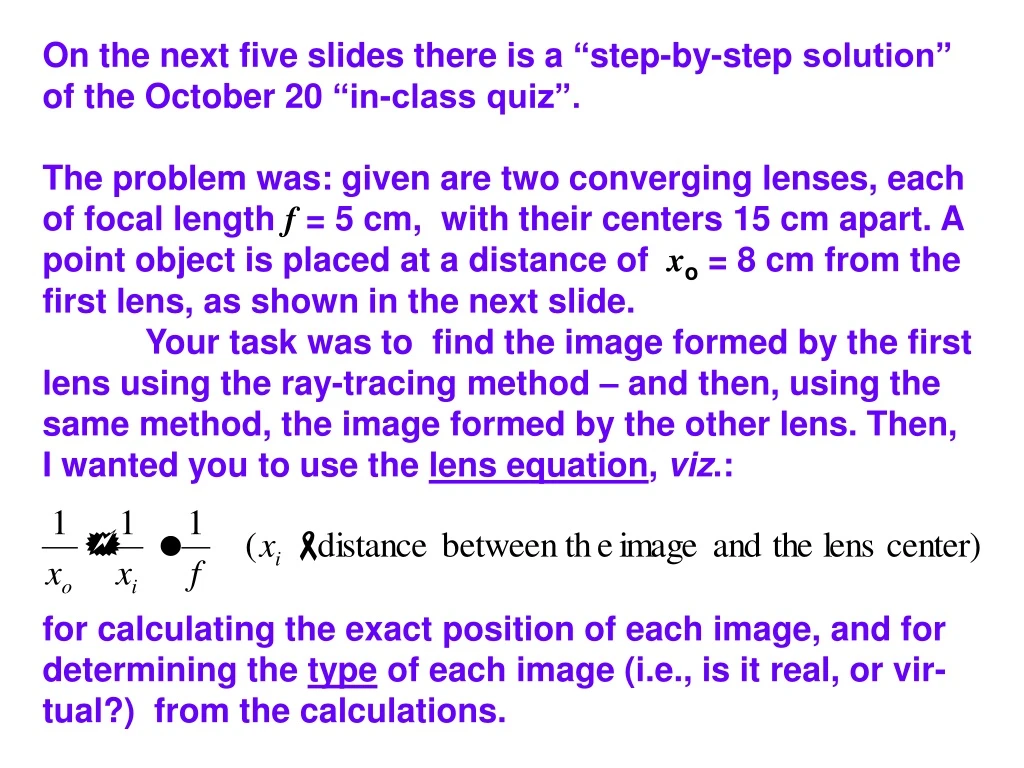
On the next five slides there is a “ step-by-step solution” of the October 20 “in-class quiz”. The problem was: given are two converging lenses, each of focal length f = 5 cm, with their centers 15 cm apart. A point object is placed at a distance of x o = 8 cm from the

E N D
On the next five slides there is a “step-by-step solution” of the October 20 “in-class quiz”. The problem was: given are two converging lenses, each of focal length f = 5 cm, with their centers 15 cm apart. A point object is placed at a distance of xo = 8 cm from the first lens, as shown in the next slide. Your task was to find the image formed by the first lens using the ray-tracing method – and then, using the same method, the image formed by the other lens. Then, I wanted you to use the lens equation, viz.: for calculating the exact position of each image, and for determining the type of each image (i.e., is it real, or vir- tual?) from the calculations.
Finding the first image by ray tracing: Note: a positive xi value corresponds to a real image. The results from both methods are consistent! And by cal- culations:
Now, we say Thank you! to the “ red rays” – they have already done their job, we don’t need them any more. We start an entirely new ray-tracing procedure, now treating the image formed by the first lens as an object for the other lens:
The rays passing through the right lens clearly form a diverging beam – meaning that now the image is virtual. In order to find the position of the image, we have to “extra- polate” the rays, which done below using the dashed lines. The image is where the “extrapolated rays” intersect.
Finally, we can mark the position of the second image using a blue arrow – a good practice is to use a dashed arrow stem to indicate that the image is virtual. Negative distance means: virtual ima- ge, upright, at the same side of the lens as the object.