Download
1 / 63
710 likes | 1.48k Views
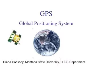
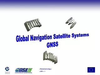
Characteristics of GPS Surveying and GPS Navigation Some characteristics of GPS Satellite Surveying are: The points being coordinated are stationary. GPS data are collected over some "observation session". Relative positioning modes of operation, and hence high accuracies.

E N D
Characteristics of GPS Surveying and GPS Navigation Some characteristics of GPS Satellite Surveying are: The points being coordinated are stationary. GPS data are collected over some "observation session". Relative positioning modes of operation, and hence high accuracies. The measurements are made on the L-band carrier wave, hence requiring special instrumentation and software. Mostly associated with the traditional surveying and mapping functions. Some characteristics of GPS Satellite Navigation are: The points being coordinated are generally in motion. GPS is collected for an "instant", and the solution is obtained in real-time. Absolute and relative positioning modes of operation, of comparatively low accuracy. The measurements are typically made on the PRN codes, and requires the processing of pseudo-range data. Mostly associated with defining safe passage of ships and aircraft. GPS Methods
GPS Positioning Modes • The main positioning modes for GPS surveying and navigation are (section 2.4.1): • ABSOLUTE or POINT positioning: coordinates are in relation to a well-defined global reference system. • DIFFERENTIAL or RELATIVE positioning: coordinates are in relation to some other fixed point. In GPS surveying this is referred to as baseline determination. • STATIC positioning: coordination of stationary points, either in absolute or relative mode. This is generally synonymous with the SURVEYING mode of positioning, based on the analysis of carrier phase observations. • KINEMATIC positioning: coordination of moving points, either in absolute or relative mode. This is generally the NAVIGATION mode of positioning, based on pseudo-range observations.
Integrated carrier beat phase data is very precise, any contamination by systematic errors is of greater concern. Appropriate processing techniques must t be used. primary drawback is its range "ambiguity". In GPS surveying the major biases are accounted for in the following ways: Differencing data collected simultaneously from two or more GPS receivers, to several GPS satellites, between satellites and between receivers. This eliminates, or significantly reduces, most of the biases. All position results are therefore expressed relative to (fixed) datum stations. The "ambiguity" bias is often estimated, though a weaker solution can be obtained from the appropriate triple-differenced observable (section 6.3). distinctions in data processing (minimise the effect of biases in the measurements) Pseudo-range data is relatively "noisy the significant biases are accounted for In the point positioning mode, satellite clock error is ignored, (smaller than the measurement noise) Receiver clock error is estimated in real-time through redundant measurements, all data is contaminated by the same bias. In the relative positioning mode, all satellite and propagation biases are significantly reduced. In SURVEYING mode the receivers are stationary, data is collected over some observation period permits the ambiguities to be reliably estimated strong solution obtained. There are alternative means of estimating ambiguities that permit real-time kinematic baseline determination to be carried out as well.
GPS Survey Solution: • fundamental unit of a GPS solution is a 3-D baseline vector joining the antennas of two GPS receivers that have been tracking simultaneously the same satellites. • One end of the baseline is held "fixed" (its coordinates are assumed known), and the other station's coordinates are determined relative to it (in effect, the baseline components are estimated). • Solutions may be obtained from ambiguity-free or ambiguity-fixed double-differenced data solutions, with different resultant accuracies and reliabilities • All results refer to the antenna phase centres, and the height of antenna and any offsets must be applied in order to reduce the coordinates to the ground marks.
The most convenient coordinate system is that provided by the rectangular Cartesian system. Cartesian components can be easily transformed at the result presentation stage GPS phase processing result in relative 3-D coordinates. 3-D baseline components that are computed a minimum of one station held fixed in a GPS adjustment GPS pseudo-range solutions are single point absolute solutions 3-D coordinates are independently determined for each receiver not as accurately determined often used to provide apriori values for the subsequent phase solutions. THE NATURE OF GPS SOLUTIONSmost distinctive feature of GPS surveying:determination of 3-D coordinates All results relate to the GPS antenna phase centres must be corrected to the groundmark by applying the antenna height and eccentric station offsets. All results are, nominally, referred to the WGS84 reference system.
SETTING UP THE SOLUTIONinitialising a triple- or double-differenced data solution • Defining the apriori groundmark coordinates, • including that for the "datum" station to be held fixed (for example, from a pseudo-range point position solution, or a triple-difference phase solution, or a previous solution when "chaining" baselines). This involves correctly setting up the station file (usually from the recorded field data), with information on antenna height, etc. • Identifying the ephemeris file to be used (may be a Navigation Message file, or the Precise Ephemerides). • Any satellites to be excluded from solution (for example, because of known health problems). • Identifying the baseline to be processed, by selecting the data files to be used (generally from a database of GPS files). • Inputting the standard deviation of the differenced observations. • If option is available for taking correlations into account, this may be exercised • . • Minimum elevation cutoff angle for data culling to low satellites. • Data selection for solution (all data or some sample rate, for example every 5th data epoch). • Tropospheric refraction model for bias may be activated, based on input met data or "standard atmosphere" values. • Dual-frequency processing options to be exercised. • Whether to attempt ambiguity resolution or not (in the case of double-differenced solution), and the test/validation parameters associated with the alg
Carrier phase • wavelengths of the carrier waves are very short -- approximately 19cm for L1 and 24cm for L2 – • 1-2% of the wavelength, this means that carrier phase can be measured to millimetre precision • a phase measurement is "ambiguous" as it cannot discriminate one (either L1 or L2) wavelength from another • time-of-transmission information for the L-band signal cannot be imprinted onto the carrier wave
basic phase measurement is therefore in the range 0° to 360°
TWO MEANS BY WHICH THE CARRIER WAVE CAN BE RECOVERED FROM THE INCOMING MODULATED SIGNAL • Reconstruct the carrier wave by removing the ranging code and broadcast message modulations • the ranging codes (C/A and/or P code) must be known. The extraction of the Navigation Message can then be easily performed by reversing the process by which the bi-phase shift key modulation was carried out in the satellite • Squaring, or otherwise processing the received signal without using a knowledge of the ranging codes • no knowledge of the ranging codes is required. More complex signal processing is required to make carrier phase measurements on the L2 signal under conditions of Anti-Spoofing
Integrated Carrier Beat Phase • Raw carrier phase measurements are generally the by-product of all GPS receivers • cannot be used as "range" observations because they are ambiguous, and furthermore, the ambiguity changes continuously • It is very difficult to resolve the continuously changing unknown ambiguity in a navigation solution (as can be done in the case of the receiver clock bias).
INTEGRATED CARRIER PHASE • possible to keep track of the number of whole wavelengths of the carrier wave as it is sampled within a phase-lock loop fractional phase (measured as an angle in the range 0° to 360°, where 360° corresponds to about 19cm for the L1 phase and 24cm for the L2 phase CR is the current reading on a zero-crossing "counter“ only registers the number of whole cycles since lock-on when the counter had an initial value of CRo (usually zero). in square brackets is an integer. The additional electronics to count the whole cycles since lock-on is the identifying characteristic of GPS "surveying" receivers.
INTEGRATED CARRIER PHASE AND THE AMBIGUITY TERM. • nji is the ambiguity term, v contains all the biases and errors affecting this measurement (f0 / c) scales range into units of cycles. Note that nji is assumed to be constant over time, for a particular receiver-satellite combinationTo convert this phase observation into range, • the cycle ambiguity has to be determined. • If the integer nji can be correctly determined, • then the resulting "phase-range" (or "carrier-range") will be a very precise range (at the level of a few millimetres).
Spreading and de-spreading the spectrum of the carrier wave . spread spectrum signal is received at the GPS antenna, the signal power is below the background noise the ranging code modulations are removed the satellite signal collapses into the original very narrow carrier frequency band signal power is again boosted well above the background noise
mix a locally generated sine wave at the same frequency as the "reconstructed" received carrier (modulated only by the Navigation Message), the broadcast message can then be extracted. The incoming and receiver-generated sine waves are continuously aligned within a "phase-lock loop"
Periodic sampling of the phase of the local carrier provides the carrier beat phase observable • although useful for some applications such as the "phase smoothing" of pseudo-ranges, • still not suitable for survey applications. • more useful carrier phase observable can be constructed through the "integration" of carrier phase measurements
Measurement of carrier beat phase on L2 by this technique requires a knowledge of the P code generating algorithm. • Under the policy of Anti-Spoofing, the Y code is secret and hence cannot be used in this code-correlating mode. • easiest option to use the "squaring" technique (or some variation of it) to make L2 phase measurements. • the primary advantage of the code-correlating approach is that it results in a far better signal-to-noise ratio, • hence better quality measurements, than any other signal processing technique.
Reconstructing the carrier wave and extraction of pseudo-range data.
Extracting carrier phase from incoming GPS signals by carrier wave squaring .
PROCESSING OF DIFFERENCED DATA ultimate aim to obtain an ambiguity-fixed solution Triple- and double-differenced data solutions have different strengths and weaknesses Triple-, double- (ambiguity-free) and double-differenced (ambiguity-fixed) solutions represent a hierarchy of processing strategies that are generally applied in sequence: first the triple-differenced solution, through to the double-differenced solutions,
The triple-differences solution algorithm • Difference epoch data between-satellites, form double-differences. • Difference double-differences between epochs at some sample rate (for example, every 5th observation epoch), form triple-differences. • Assume all triple-difference observations are independent when forming Weight Matrix (no correlations taken into account), define P matrix. • Form Observation Equations, construct the A matrix. • Accumulate Normal Equations, scaled by the Weight Matrix ATPA. • At end of data set, invert Normal Matrix and obtain geodetic parameter solution, = (ATPA)-1.ATP . • Update parameters. • Optionally scan triple-difference residuals for cycle slips in double-difference observables
The double-difference solution algorithm: • Difference epoch data between-satellites, form double-differences. • Apply data reductions, such as a troposphere bias model. • Construct Weight Matrix (depending on whether correlations are to be taken into account), define the P matrix. • Form Observation Equations --> construct the A matrix. • Accumulate Normal Equations, scaled by the Weight Matrix ATPA. • At end of session, invert Normal Matrix and obtain geodetic and ambiguity parameter solution, = (ATPA)-1.ATP . • Update parameters. • Decide (a) iterate solution, or (b) iterate solution only after ambiguity resolution attempted
AMBIGUITY RESOLUTION • What is ambiguity resolution? • The mathematical process of converting ambiguous ranges (integrated carrier phase) to unambiguous ranges of millimetre measurement precision ... • For conventional GPS surveying, corresponds to converting real-valued ambiguity parameter values to the likeliest integer values
AMBIGUITY RESOLUTION • determining the value of this unknown initial (integer) ambiguity is an important task of GPS data reduction software • only possible after all biases are eliminated or otherwise accounted for to better than one cycle (20cm wavelength on L1
The ambiguity-fixed solution algorithm: • Difference epoch data between-satellites, form double-differences as before but without ambiguities as solve-for parameters. • Apply data reductions, such as a troposphere bias model. • Construct Weight Matrix (depending on whether correlations are to be taken into account), define thePmatrix. • Form Observation Equations, construct theAmatrix. • Accumulate Normal Equations, scaled by the Weight MatrixATPA. • At end of session, invert Normal Matrix and obtain geodetic parameter solution, = (ATPA)-1.ATP . • Update parameters. • This process can be iterated to resolve other ambiguities until (a) all have been resolved (and "fixed" to integers), or (b) no more can be reliably resolved.
Change in quality of baseline components in an ambiguity-free compared to an ambiguity-fixed solution phase data collected beyond the minimum necessary to ensure an ambiguity-fixed solution is obtained has almost no influence on the final results sequential transition from an 100% ambiguity-free solution to an 100% ambiguity-fixed solution
Ambiguity Resolution • In region A the precision (and accuracy) of the coordinates steadily improves as more data is collected. • As soon as sufficient data is available to resolve the ambiguities (at epoch 15) a dramatic improvement in the coordinate parameter precisions is evident. • In region B, when the unambiguous range data (based on precise phase measurements now converted to precise range observations) are processed, there is no improvement in the quality of the coordinate solution, and in effect there is no real justification for continuing to collect data past epoch 15. • If enough data is collected over an observation session, the precision of the ambiguity-free baseline solution will steadily improve, converging to that obtained from an ambiguity-fixed solution.
Ambiguity Resolution • conventional static GPS surveying the data is post-processed and it is therefore not known apriori at what point (or even if) sufficient data has been collected to ensure an ambiguity-fixed solution is obtained. Hence conservative observation session lengths (not less than 30 minutes, and usually 60 minutes) are recommended
address the following questions • How can the length of the observation span required to ensure ambiguity resolution be made significantly shorter than for the case of conventional GPS surveying? • Are there any "tricks" to improving ambiguity resolution efficiency, particularly when observation sessions are short? • How can ambiguity resolution be made more reliable, particularly when observation sessions are short? • How can positioning using phase data be best carried out after ambiguities have been resolved? That is, how to minimise the number of times ambiguity resolution must be carried out? • How can the ambiguity resolution procedure be made so "transparent" that it may be carried out automatically, even with the receiver in motion, and whenever it is required?
several modern GPS surveying techniques • Rapid static positioning techniques. • Reoccupation techniques. • "Stop &Go"techniques. • Kinematic positioning techniques
Kinematic Procedures: • when the entire process of ambiguity resolution (or initialisation) and "carrier-range" positioning takes place while the antenna is in motion. • Otherwise it is identical to the "stop & go" procedure.
Rapid Static Procedure: • employs a sophisticated ambiguity search procedure to test many sets of candidate ambiguity sets and select the (most likely) correct one, using only a small amount of data. (Hence this method strives to narrow the width of region A in figure above, and to predict the point at which ambiguity resolution occurs with high reliability.) If the ambiguity search procedure fails, the technique gives poor baseline results because there is insufficient data to obtain a good quality ambiguity-free solution. The method can only be applied on static baselines.
RAPID STATIC GPS SURVEYINGStatic positioning with short observation times of 5-20 minutes (vs 1-2 hours) ... giving centimetre accuracies • fast-static or quick-static • Observation time requirements:These are significantly shorter than for conventional GPS surveying, and are a function of baseline length, number of satellites being tracked and satellite geometry. Typically the receivers need only occupy a baseline for a period of 5-20 minutes (the lower value corresponding to baselines <5km and tracking six or more satellites; the upper value for longer baselines up to 20km, and/or where tracking is to only four satellites).
Hardware requirements • Different GPS "products" have different hardware requirements. • In some systems only dual-frequency phase measurement is sufficient, • in system configurations dual-frequency pseudo-range measurements are also required. • To date there is no "mixing" of receivers and software as in the case of conventional GPS surveying. • The exact configuration is of course dependent on the software being used. • For example, if the software for rapid static is quite sophisticated then there is less reliance on specialised top-of-the-line hardware. • (For example, rapid static results have been obtained with single frequency phase data.) • for other rapid static "products", full four observable instrumentation (L1 & L2 phase, P1 and P2 pseudo-range; or L1 & L2 phase, C/A pseudo-range and P1-P2 observable) is a prerequisite. • Specialised software: The basis of this technique is the ability of the software to resolve the ambiguities (determine their integer values) using a very short observation period. There is a variety of software, with different characteristics and levels of sophistication, but the fundamental requirement is a fast ambiguity resolution capability.
field procedures are much like those for conventional static GPS surveying • occupation times are shorter, the baselines should be comparatively short, the satellite geometry favourable and signal disturbances such as multipath should be a minimum • not possible to define exactly how much data needs to be collected in order to produce quality baselines every time, and with high reliability !!? • If the real-time mode is employed (the base station transmits tracking data to the mobile unit where it is processed immediately) then the "data quantity gamble" for rapid static GPS surveying can be overcome
Such a technique is well suited for short range applications such as control densification and engineering surveys, or any job where many points need to be surveyed (see Figure below). Unlike the "kinematic" and "stop & go" techniques there is no need to maintain lock on the satellites when moving from one station setup to another
REOCCUPATION GPS SURVEYING TECHNIQUESCentimetre positioning accuracy with two occupations per site, each for a short static observation period (few minutes) ... • This technique exploits changes in satellite geometry across conventional observation sessions. Phase data from two short sessions of just a few minutes in length (perhaps up to 10 minutes), collected about one hour apart is sufficient to ensure a good quality ambiguity-free solution. • The roving receiver must revisit the same point one or more hours later • Two separate sets of ambiguities must be estimated, one for the first session, the other for the second session. It is not necessary for the same constellation of satellites to be observed for both sessions. • It is the technique that fits somewhere between conventional static and "kinematic" techniques in terms of productivity. • It is faster than conventional static, but it is not as accurate, if only an ambiguity-free solution is usually obtained. An ambiguity-fixed solution, if obtained, is more accuracte. • It is an alternative to the "rapid static" technique, no faster but also not as accurate unless ambiguities are resolved (in which case it is identical to the "rapid static" technique). • It is more flexible than the "stop & go" or "kinematic" techniques as it does not require that satellites be tracked while the receiver is being moved from site to site.
STOP & GO" GPS SURVEYING TECHNIQUESCentimetre accuracy positioning during very short static observation periods (<1minute) ... receiver moves carefully from point to point • This is a true kinematic technique because the receiver continues to track satellites while it is in motion. It is known as the "stop & go" (or semi-kinematic) technique because the coordinates of the receiver are only of interest when it is stationary (the "stop" part), but the receiver continues to function while it is being moved (the "go" part) from one stationary setup to the next.
STOP & GO" GPS SURVEYING TECHNIQUES • The initial ambiguity resolution: This is carried out (generally in static mode) before the "stop & go" survey commences. The determination of the ambiguities can be carried out using any method, but in general it is one of the following: • A conventional static (or "rapid static") GPS survey determines the baseline from a fixed receiver to the first of the uncoordinated sites occupied by the second "roving" receiver. An ambiguity-fixed solution provides the integer values of the ambiguities. • Setup both receivers over a known baseline, possibly surveyed previously by GPS. • Employ a procedure known as "antenna swap". Two tripods are setup a few metres apart, each with an antenna on them (the exact baseline length need not be known). Data is collected by each receiver for a few minutes (tracking the same satellites). The antennas are then carefully lifted from the tripods and swapped, that is, the receiver 1 antenna is placed where the receiver 2 antenna had been, and visa versa (see Figure below). After a few more minutes the antennas are swapped again (Figure 1). • The most versatile, and most recent, technique is to resolve the ambiguities "on-the-fly" (that is, while the receiver is turned on but the receiver/antenna is moving).
STOP & GO" GPS SURVEYING TECHNIQUES • The receiver in motion: Once the ambiguities have been determined the survey can begin. The roving receiver is moved from site to site, collecting just a few minutes of phase data. It is very important that the antenna continues to track the satellites. In this way the resolved ambiguities are valid for all future phase observations, in effect converting the ambiguous carrier phase data to unambiguous "carrier-range" or "phase-range" data (by applying the integer ambiguities as data corrections). As soon as the signals are disrupted (causing a cycle slip) then the ambiguities have to be reinitialised (or recomputed). This can most easily be done by bringing the receiver back to the last surveyed point, and redetermining the ambiguities by the "known baseline" method. • The stationary receiver: The "carrier-range" data is then processed in the double-differenced mode to determine the coordinates of the roving receiver relative to the static reference receiver. The trajectory of the antenna is not of interest, only the stationary points which are visited by the receiver. • The technique is well suited when many points close together have to be surveyed, and the terrain poses no significant problems in terms of signal disruption (usually an audible signal is emitted by the receiver when it has lost lock on the satellites). The survey is carried out in the manner illustrated in the Figure 2 below, and the ambiguities reinitialised using any of the techniques
STOP & GO" GPS SURVEYING TECHNIQUES An additional requirement is that the stationary reference receiver must continue to track all the satellites being tracked by the roving receiver. The accuracy attainable is about the same as for the "rapid static" technique. As with the"reoccupation" technique, the receiver must have the ability to handle data files from several different sites. The software then has to sort out the recorded data for the different sites, and to differentiate the "kinematic" or "go" data (not of interest) from the "static" or "stop" data (of interest). It can be implemented in real-time if a communications link is provided to transmit the "carrier-range" data from the reference receiver to theroving receiver(s). One particular negative characteristics of this technique is the requirement that phase lock must be maintained by the roving receiver as it moves from site to site. This requires special hardware mounts on vehicles if the survey is carried out over a large area.
KINEMATIC GPS SURVEYING TECHNIQUESCentimetre positioning accuracy of moving antenna • initially determining (and redetermining after a cycle slip) the ambiguities "on-the-fly". Today the "kinematic" GPS surveying technique is undergoing tremendous improvement and "on-the-fly" ambiguity resolution is a routine procedure (though not yet by any means an entirely foolproof one!), making kinematic surveying techniques ideal for road centreline surveys, hydrographic surveys, airborne applications, etc.
trends in "kinematic" surveying • There is a blurring of the distinction between "kinematic GPS surveying" and "kinematic GPS navigation". The former is carrier phase based (actually "carrier-range" data), whereas the latter has usually been taken to refer to pseudo-range based positioning. However, nowadays more navigation instruments are using "carrier phase smoothed pseudo-ranges" (section 6.4.11). However, it is still valid to distinguish these techniques as "decimetre accuracy positioning" on the one hand, and "submetre accuracy positioning" on the other hand. • There is trend to using a combination of both phase and pseudo-range data within the positioning algorithm itself, precise C/A code ranges as well as P code pseudo-ranges. • There is an increasing sophistication of the algorithms, for example, incorporating Kalman filters. • There are techniques based on single frequency data, as well as those top-of-the-line procedures requiring dual-frequency data. • "On-the-fly" ambiguity resolution techniques will probably all other "kinematic" techniques (and possibly the "rapid static" and "reoccupation" techniques as well). • Real-time operation ("real-time kinematic" -- RTK) is increasingly popular as it offers considerable advantages in that the results are available immediately, in the field, but it is still a challenge and operates under a number of significant constraints.
ISSUES RELATING TO MODERN GPS SURVEYING • CONVENTIONAL (STATIC) GPS SURVEYING: • Advantages • Highest accuracy • Robust technique • Ambiguity resolution not critical • Minor impact of orbit error and multipath • Undemanding of hardware and software • Disadvantages • Long observation sessions • Inappropriate for engineering and cadastral applicatio
MODERN GPS SURVEYING • : • Advantages • Higher accuracy than pseudo-range solutions • Appropriate for many survey applications • High productivity • Similar procedures to modern terrestrial surveying • Disadvantages • Special hardware and software • Susceptible to orbit, atmospheric multi-path disturbances • Higher capital costs • Ambiguity-fixed or continuous lock required • Two negative characteristics of these modern GPS techniques are: • They are susceptible to multipath disturbance to an axtent (affecting the receiver signals during both the kinematic and static stages of the tracking) than the conventional static technique. Multipath during the ambiguity resolution period is especially dangerous, as wrong ambiguities may result. • The results from short observation sessions are more sensitive to bad satellite geometry (large GDOP) than the conventional static techniq
Combining conventional GPS and modern GPS survey techniques.
All static • Observation 1010-1111 • 45 min • Move from 1010 to 2222(setup)13 min • Observation 1111-2222 • 45 min • Move from 1111 to 3333(setup)16 min • Observation 2222 to 3333 • 45 min • Move from 2222 to 4444(setup)14 min • Observation 3333-4444 • 45 min • Move from 3333 to 1010(setup)16 min • Observation 1010-4444 • 45 min
Static and stop/go • Observation 1010,1111,1011 • 45 min • Move time and setup • 23 min • Observation 1111,2222,3333 • 45 min • Move time and setup • 16 min • Observation 4444,3333,1011 • 45 min • Move time and setup • 22 min • Observation 1010,4444,2222 • 45 min • 241
Mixed mode- 2 references • 79 minutes -19 minutes (last re-observation of station 1111) = • 68 minutes • Checks: Repeatability. Allows for Free Least Square Adjustment.
variety of combinations of several modern GPS surveying techniques which are possible