Download
1 / 63
650 likes | 924 Views
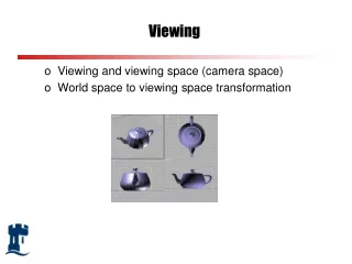
Viewing. How to see the object Type of object view How to set the view for CG The shadow creating. Type of Views Examine how an app viewer can create a particular view within OpenGL Use model-view matrix to switch from world frame to camera frame: camera at origin

E N D
Viewing How to see the object Type of object view How to set the view for CG The shadow creating suriyong l.
Type of Views • Examine how an app viewer can create a particular view within OpenGL • Use model-view matrix to switch from world frame to camera frame: camera at origin • Preferred projection type : • parallel, perspective suriyong l.
Viewing Principle of view • Classical view and computer view are Similar COP at infinity COP: Center Of Projectionex. eye , camera lens, for CG: the camera frame DOP: Direct OP - view at infinite distance suriyong l.
COP condition • Finite distance view • perspective view • Infinite distance view • Parallel view • Limiting case of perspective view • Treat as separate case • API support both view • User easily switch between view • Use planar geometric projection viewing method: • Object project on planar surface (plane and projection lines) • 2 types of view for CG but classical permit more than one viewer one-, two- etc. suriyong l.
Classical views Classical view • Underlying notion of principal face • Object is composed of a number of planar faces front, back, top, bottom, etc. suriyong l.
Orthographic projection Temple and three multiview orthographic projections Orthographic projections • An Orthogonal view • Projectors are perpendicular to projection plane • Multiview Orthographic projection • Projection plane is parallel to one of the principle faces, usually 3 faces suriyong l.
Orthographic properties • Preserve both distances and angles: • No distortion in shape • Projectors perpendicular to plane • Projection plane is parallel to one principal of object face • Applied in drawings suriyong l.
Axonometric projection • Plane rotational orthogonal projection • Plane is not perpendicular to 1 face • Special case • Isometric : • plane is places symmetrically with 3 simple faces • Dimetric: • plane is places symmetrically with 2 simple faces • Trimetric • No faces are places symmetrically with plane suriyong l.
Axonometric projections. (a) Construction of trimetric-view projection. (b) Top view. (c) Side view. Axonometric views suriyong l.
Types of orthographic view • Oblique view (planar face view) • Axonometric view suriyong l.
Oblique view (a) Construction. (b) Top view. (c) Side view. Oblique View • Projector make an arbitrary to projecting plane • Able to see more than 1 face at the same time • Most difficult to draw by hand • Lens parallel to plane • Unnatural suriyong l.
Classical perspective views: The (a) three-, (b) two-, and (c) one-point perspectives Perspective view Perspective View • Diminution of size • Unable to measure • Real-lookingimage • For classical perspective 1-, 2- or 3- point perspective suriyong l.
Initial camera position. Viewing with a computer • OpenGL View • Perspective camera – 1 point of view • Orthogonal camera suriyong l. Imaging using the default camera.
Movement of the camera and world frames. (a) Initial configuration. (b) Configuration after change in the model view matrix Initial camera position. Positioning of the camera • Convert reference of model frame to camera frame • First at point P (both frame at vertex) • Last at point Q • Camera frame C suriyong l.
Suppose to see object at +x direction glMatrixMode(GL_MODELVIEW); //Initialize matrix_mode to Model_view glLoadIdentity(); glTranslatef(0, 0, -d); // Translate far from origin with distance d glRotatef(90.0, 0.0, 1.0, 0.0); // move camera to x axis (rotate around +y) suriyong l.
Create Isometric view • Object moving • Transform object to isometric view type • Camera moving • Move the camera to the isometric view type suriyong l.
Object moving // Assume that we have 2 unit cube glMatrixMode(GL_MODELVIEW); glLoadIdentity(); glTranslatef(0.0, 0.0, -d); // move camera backward glRotatef(35.26, 1.0, 0.0, 0.0); // Rotate around x axis (35.26o) // Point (-1, 1, 1) move to (0,0, √2) glRotatef(45.0, 0.0, 1.0, 0.0); // Rotate around y axis (45o) glOrtho(…); // view clipping The (-1, 1, 1) is rotate to the new point (0, 0, √2) and translate to -d suriyong l. positive z-axis view x-axis view
Create an Isometric view • Symmetrically rotate object to see 3 faces together • Rotate about the y-axis (45o) and x-axis (-35.26o) consequently • Move away from WCS with distance d M = Ry(45) .Rx(-35.26). T(-dz) suriyong l.
Camera moving Two Viewing APIs (Normalization transformation process) Camera frame. Start at world frame, camera at origin look to –z direction, define the projection point on projection plane as VRP (View Reference Point) Specify VRP – View Reference Point with user’s function set_view_reference_point(x, y, z); Specify camera orientation: fix the camera orientation - user’s function VPN (View Plane Normal vector - n) set_view_plane_normal(nx, ny, nz); VUP (View UP vector) : up direction set_view_up(vup_x, vup_y, vup_z); suriyong l.
Let p is VRP View plane normal (n) Determination of the view-up vector. Specify vfromVUP Projection Create ufrom v, ncross product u = v x n Get new orthogonal coordinate systemu-v-ncalledviewing-coordinate system matrix that does change frame called view-orientation matrix VUP Target: Fine the isometric matrix which composed of translation and rotation V = RT // V: the isometric matrix Move the camera to the VRP by translation matrix let T (-x, -y, -z) suriyong l.
suriyong l. We need matrix in the form of inverse thus, R = M-1 = MT ; R is the rotation matrix Finally, multiply by T then Note: Translation matrix is on the right, first on the left second derivation, camera was specified in the world frame both have similar forms
Look-at positioning. The Look-At function • Isometric viewing function • Use model of VRP, VPN and VUP gluLookat(eyex, eyey, eyez, atx, aty, atz, upx, upy, upz); eyex, eyey, eyez : location of VRP atx,aty, atz : target object (VPN = [atx-eyex, aty – eyey]) upx, upy, upz : (VUP = [upx-eyex, upy-eyey]) suriyong l.
OpenGL application sequence glMatrixMode(GL_MODELVIEW); glLoadIdentity(); gluLookAt(eyex, eyey, eyez, atx, aty, atz, upx, upy, upz); // define objects here suriyong l.
Roll, pitch and yaw Elevation and azimuth Other Viewing APIs suriyong l.
Perspective Projection Condition: COP at the origin Camera point to –ve Z axis We will consider the first case in detail Two possibility of camera for perspective projection (a) view plane parallel to lens and normal to z axis (b) view plane not parallel, but lens orthogonal to z axis suriyong l.
Three views of perspective projection. (a) Three-dimensional view. (b) Top view. (c) Side view. • Calculation step • Let point in space is located at x, y, z • Projection plane is perpendicular to –z axis and located at z = d • Project that point to projection plane, let’s say xp, yp, zp • Summary • Non uniform shortening • The closer of object, the size is much more reduce suriyong l.
Projection pipeline. Using homogeneous coordinate Perspective projection transformation Divided by 4th component Then suriyong l.
Orthogonal projection Orthogonal Projection • Special case of perspective projection • Projectors are perpendicular to view plane • Rather than cop at infinity, let z = 0 then Transformation matrix form suriyong l.
Definition of a view volume Front and back clipping planes Projection in OpenGL More property for camera: angle of view Only objects that fit in within angle of view of the camera appear in the image suriyong l.
Perspective in OpenGL 2 function for specifying perspective view glFrustum(xmin, xmax, ymin, ymax, near, far); Note: near, far are +ve, measured from COP (at z = 0) glFrustum(left,right, bottom, top, near, far); suriyong l. Specification of a frustum
We must select the matrix mode glMatrixMode(GL_PROJECTION); glLoadIdentity(); glFrustum(xmin, xmax, ymin, ymax, near, far); Note: no need for xmin, xmaxor ymin, ymax are symmetry to z axis Many application specify the angle of view projection plane need not to be square suriyong l.
gluPerspective(fovy, aspect, near, far); // For specifying angle of view fovy: angle between the top and bottom aspect: the ratio of w divided by h of projection plane near, far : plane specified as glFrustum Specification using the field of view. suriyong l.
Parallel view in OpenGL Use function glOrtho glOrtho(xmin, xmax, ymin, ymax near, far) Or glOrtho(left, right, buttom, top, near, far) Orthographic viewing. suriyong l.
The z-buffer algorithm. Hidden surface removal • Many algorithm • Object-space algorithm: object’s surface has order • Image space algorithm: (z-buffer algorithm) • check the depth if surfaces are overlap suriyong l.
Function use for removal Initializing the depth buffer and enable the hidden surface removal glutInitDisplayMode(GLUT_DOUBLE | GLUT_RGB | GLUT_DEPTH); glEnable(GL_DEPTH_TEST); Clearing buffer for new rendering glClear(GL_DEPTH_BUFFER_BIT); suriyong l.
Culling (selection) • Removing all the surfaces pointing away from viewer (render only the one facing the viewer) • By enable culling glEnable(GL_CULL_FACE); • Work with convex object an z buffer • If n cubes are passed trough pipeline, 6n faces are passed trough pipeline • If culling, half of the surface is eliminated suriyong l.
Walk trough a scene Use key to relocation the camera void keys(unsignedchar key, int x, int y) { if(key == ‘x’) viewer[0] -= 1.0; // viewer[] is predefined array if(key == ‘X’) //to hold camera position viewer[0] += 1.0; if(key == ‘y’) viewer [1] -= 1.0; if(key == ‘Y’) viewer[1] += 1.0; if(key == ‘z’) viewer[2] -= 1.0; if(key == ‘Z’) viewer[2] += 1.0; glutPostRedisplay(); } suriyong l.
void display(void) { glClear(GL_COLOR_BUFFER_BIT| GL_DEPTH_BUFFER _BIT); glLoadIdentity(); // use gluLookAt to define camera view gluLookAt(viewer[0], viewer[1], viewer[2], 0.0, 0.0, 0.0, 0.0, 1.0, 0.0); glRotatef(theta[0], 1.0, 0.0, 0.0); glRotatef(theta[1], 0.0, 1.0, 0.0); glRotatef(theta[2], 0.0, 0.0, 1.0); colorcube(); glFlush(); glutSwapBuffers(); } suriyong l.
//Use “glFrustum” to specify the camera lens void myReshape (int w, int h) { glViewport (0, 0, w, h); glMatrixMode(GL_PROJECTION); glLoadIdentity(); if (w<= h) glFrustum (-2.0, 2.0, -2.0*(GLfloat) h/ (GLfloat) w, 2.0*(GLfloat) h/ (GLfloat) w, 2.0, 20.0); else glFrustum(-2.0, 2.0, -2.0*(GLfloat) w/ (GLfloat) h, 2.0*(GLfloat) w/ (GLfloat) h, 2.0, 20.0); glMatrixMode(GL_MODELVIEW); } suriyong l.
Projection normalization Convert all projections into orthogonal projection Distort the objects to the same as the desire projection of the original object Using homogeneous coordinate matrix by concatenate this matrix as shown Normalization transformation Predistortion of objects. (a) Perspective view. (b) Orthographic projection of distorted object. suriyong l.
Orthogonal-Projection matrices Parallel viewing All point project in to the same point on projection plane If clipping volume is defined by 6 plane Called (canonical view volume) glMatrixMode(GL_PROJECTION); glLoadIdentity(); glOrtho(-1.0, 1.0, -1.0, 1.0, -1.0, 1.0); Use function call Near plane is at z = 1, back of camera Far plane is at z = -1 front of camera suriyong l.
Let set glOrtho(xmin, xmax, ymin, ymax, Near, Far ); Canonical view: Left side: xmin Right side xmax Top : ymax Bottom: ymin Front clipping plane at z = -near Back clipping plane at z = -far Mapping a view volume to the canonical view volume suriyong l.
Effect: Former defined vertices are convert to canonical view Projection matrix is determined by type of view and the view volume is defined by glOrtho Affine transformations for normalization . <- In term of near and far suriyong l.
Oblique Projection Oblique clipping volume Oblique projection suriyong l. Oblique projection. (a) Top view. (b) Side view
Effect of shear transformation Breaking to Orthogonal projection and shearing matrix Conclusion: oblique is done by shearing and projection suriyong l.
Last Scaling and transformation Total process of oblique canonical projection matrix suriyong l.
Perspective transformation • Like previous transformation • First : transform to canonical view (normalization) • Suppose the angle of view is 90 O suriyong l. Simple projective projection
Normalized oblique projection Former perspective projection matrix at z = -1 Apply N to homogeneous coordinate q = Np With 90O angle of view we get Introduce matrix N transformation matrix suriyong l.