Download
1 / 21
210 likes | 500 Views
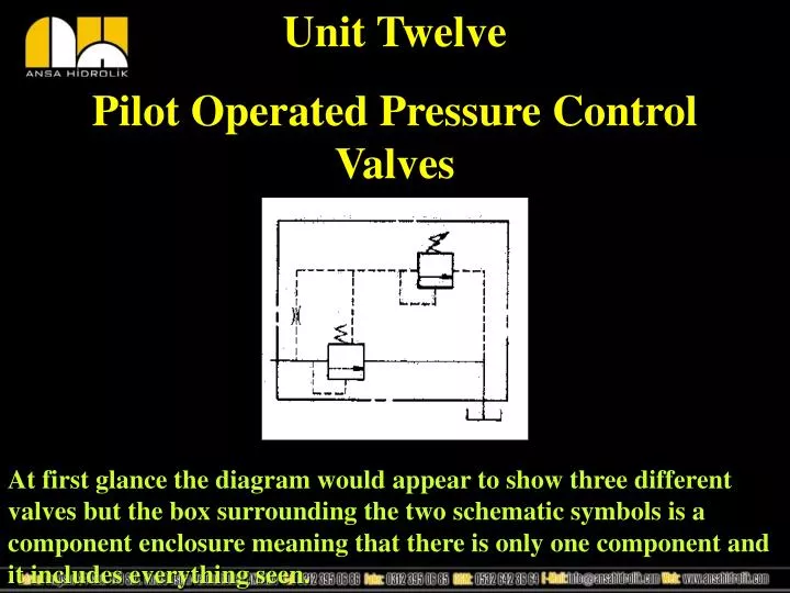
Unit Twelve Pilot Operated Pressure Control Valves. At first glance the diagram would appear to show three different valves but the box surrounding the two schematic symbols is a component enclosure meaning that there is only one component and it includes everything seen.

E N D
Unit Twelve Pilot Operated Pressure Control Valves At first glance the diagram would appear to show three different valves but the box surrounding the two schematic symbols is a component enclosure meaning that there is only one component and it includes everything seen.
Direct vs. Pilot Operated A direct acting pressure control valve is one whose sealing member is forced to open solely by the pressure of fluid. Direct acting pressure control valves are common in hydraulics as a relief valve. Pilot operated pressure control valves are actually two valves made into one. Sometimes called a “two stage” pressure control, pilot operated pressure control valves have a primary and secondary stage. When the primary stage activates
Override-Direct Operated Pressure Control Valves Override is a characteristic of a valve where the valve will momentarily create a pressure beyond its setting. This is caused by the compression of a spring. High override can damage sensitive components as well as waste energy.
Override-Pilot Operated Pressure Control Valves Pilot operated valves don’t have as much override because they use a light spring and fluid pressure to hold the valve in its normal state. The moment the fluid is released, the valve opens very fast because the light spring has little resistance.
Direct Acting Pressure Control In the illustration above, a only spring tension holds the ball against the seat. The adjustment knob, shown at the bottom, is for changing tension on the spring.
Pilot Operated Pressure Control In the illustration above both fluid and spring force hold the main poppet(main stage) closed. After the pilot relief poppet opens from system pressure, oil begins to vent from the spring side creating a pressure differential and reducing the total force holding down on the main poppet. When the pressure differential is great enough the main poppet opens quickly. It is this rapid opening capability that makes this design more efficient than the direct acting type.
Pilot Operated Pressure Control Valve Operation Initially at start up the hydraulic system would be at low pressure, for a couple of seconds, and the relief valve shown above would be closed. The orifice ensures that system pressure is “felt” on both sides of the spool. Study the illustration to become familiar with the individual components.
Pilot Operated Pressure Control Valve Operation In the illustration, the port subjected to 1000psi is the inlet port and is directed attached to the system. The port down below is connected to tank.
Pilot Operated Pressure Control Valve Operation Since the dart is biased by a stiff spring, it will take more pressure to overcome it than the spring of the main spool which is light by comparison. The action of the dart opening starts the venting process by creating a pressure differential across the main spool.
Pilot Operated Pressure Control Valve Operation Once the dart has begun to open, it will take an additional pressure build up of 25psi before the main spool opens fully. It should be noted that the main spool “throttles” in a relief valve. Main spool positioning is based on the demand for flow.
Pilot Operated Pressure Control Valve Operation While venting, the dart is completely unseated and passing oil at high pressure. With the dart open, a pressure differential exists because the oil leaving the area above the spool is greater than the oil that can flow in through the tiny orifice. When pressure drops the dart closes and oil pressure builds on the spool, closing it.
Sequence Valve Simply put, the purpose of a sequence valve is to cause a series of operations to occur in order. This normally not passing valve blocks oil to the “secondary” actuator until a preset limit of pressure is reached. When pressure is correct, the sequence valve opens and allows flow to reach the secondary actuator for movement. Unlike the relief valve, the sequence valve will open completely. Usually, a bypass check valve is included for reverse flow.
Counterbalance or Unloading Valve This valve is remotely operated. Remember that the valve is watching the sense line for pressure, not its inlet, so we can control a tremendous load but allow it to move at relatively low pressure by use of the remote pilot.
Pressure Reducing Valve The pressure reducing valve is the only normally passing pressure control used in hydraulics. Just like the pneumatic pressure regulator, the reducing valve controls pressure in hydraulic branch line circuits. Recall that we can control the clamping force of a cylinder with this valve.
Methods of Remote Control Any time the oil on top of the main spool is vented, the main spool will open. All methods of remote control work on this principle.
Remotely Operated Pressure Control Valve In the example above, the remote pilot valve serves to control the relief valve by venting the oil on top of its main spool. The remote pilot might be located some distance from the relief valve, maybe on a control panel. The other dart on the relief valve could be used for maximum pressure control of the valve.
Remotely Control of Relief Valve Schematic Representation There is no component enclosure symbol because these two valves are not physically together.
Alternative Remote Control When examine the above illustration, please remember that any time the oil is released from above the main spool, this type of valve will actuate. You could even use two way hand valve to do the job.
Differential Unloading Relief Valve This valve, unlike the others, gives us a “cut in” and “cut out” range for unloading a pump. This valve is usually used with an accumulator so that the pump may be unloaded during periods where the system is being powered by the stored volume of the accumulator.
Differential Unloading Relief Valve In a Circuit Notice the two sense lines. This valve is watching the pressure at the pump outlet as well as the accumulator. The check valve isolates the system from the pump during the unloaded periods.
Pilot Controlled Pressure Regulator Some of the control methods used in hydraulics are also used in pneumatics. Here, pilot pressure, in this case air pressure, is used to push the piston down while pressure from the secondary port pushes up on the piston. Whenever the air on top is exhausted, the valve will close.