Download
1 / 21
210 likes | 363 Views
MCHP-1 clamp and MC port opening metrology review. 6/5/08. ProE model: stb-mchp-1_vvsa1_pppl_best_fit.asm stb-fpa_mech_left_side.asm, Rep: mchp-1_clamp_metrol_pts Source data: MCHP-1 VVSA1 clamp summary.xls. T. Brown / M. Smith.

E N D
MCHP-1 clamp and MC port opening metrology review 6/5/08 ProE model: stb-mchp-1_vvsa1_pppl_best_fit.asm stb-fpa_mech_left_side.asm, Rep: mchp-1_clamp_metrol_pts Source data: MCHP-1 VVSA1 clamp summary.xls T. Brown / M. Smith
This review covers the installation clearance of MCHP-1 passing over VVSA1 • Reviewed clamp envelop-to-VV clearance assuming a 7/8” vessel services offset (slide 3 - 5) • Evaluated the clearance of metrology measured MCHP-1 clamp data moving over VV looking at the closest set of clamp points (slides 6 – 11) • Made a visual inspection of the region where the clamp distance is minimum (slide 12) • Reviewed VVSA1 as-built data (slides 12 -14) • Reviewed the assembly clearance of the second set of metrology measured clamp points and found them to be less restrictive. • A preliminary investigation of the VVSA1 / MCHP-1 port clearances has been made (slides 14 – 18) Summary: A .51 to 0.56” minimum assembly clearance occurs at Step 4 in the assembly path (based on disassembly steps). The minimum clearances occur at two locations along the Type-B MC. One area is near the midsection and one near the crest of the vessel (see slides 5 and 14).
Minimum clearance encountered during assembly 1.38” The Type-B MC winding form comes within 1.38” to the CAD defined VV surface. VVSA1 metrology measured surface points added to VV
There are no out-of tolerance points in the tightest region. Local measurement were made to confirm that all added surface components did not extend more than 1” off the surface. The maximum VV surface component offset found is 7/8”
VV / MCHP clearances In general there is 2”assembly space above the VV CAD surface. With ≤ 1” surface components, leaves a min. 1” assembly gap. Final clearance is 0.74” (1.62-7/8” VV services) 0.509” minimum clearance to a 7/8” offset of surface components 7/8” limit of surface components above vessel surface. Step 0 defines the final assembled position on this graph
Clearance ofA/B/C envelope plus clamp data to a 7/8” VV offset surface .241” 0.241” Calculated clearances between all of the MC clamp envelops and clamp metrology data to a 7/8” offset of the VV surface with a minimum distance found at metrology clamp data at the type-B MC.
MCHP-1 (left side) MC clamp metrology data shown over the VVSA1 VV. The above figures shows Verisurf metrology points of the MC clamps that were measured along with spheres placed at the closest distances to the VV surface.
Closest distance VV-to-probe surfaces is 0.785”; 15 mm Ø probe (0.59”) Minimum distance of VV services to clamp = 0.785 + .59 -7/8 = 0.50” in its final position.
Clamp distance is measured from a 7/8" offset of the CAD VV surface. The vessel as-built information also needs to be factored into the clearance calculations. Evaluation of metrology measured clamp data tracking the closest group of points (see nest slide). Step 1 Step 4 (.241”) See next two slides
Closest set of points at Step 1 Clearance values shown includes an assumed 7/8” vessel service stand-off .525 At Step 1
Clearance values shown includes an assumed 7/8” vessel service stand-off. A visual inspection of VVSA1 shows the a 0.6” hose and 0.8” max. clamp offset in this area. Closest set of points at Step 4 N-6 .68 .443 .241 M-9 .465 N-8 N-9 O-6 Step 4 Locating loop numbers
AS-BUILT Measurements All measured points in this area are negative, located inside the vessel surface Although the MTM and PPPL points are slightly different the size the offset is about the same (see next few slides) PPPL data MTM data
PPPL - yellow spheres MTM - blue spheres
Points in red are as-built metrology points which are all negative (below the CAD surface) The minimum expected clearance in this area then should be 0.56” [.241 + .25 + (7/8 - .8) = .56 ] -.25 to -.375” -.25 to -.38” -.23 to -.24”
Clamp distance is measured from a 7/8" offset of the CAD VV surface. The vessel as-built information also needs to be factored into the clearance calculations. The graph below tracks the next set of closes MC clamp points.
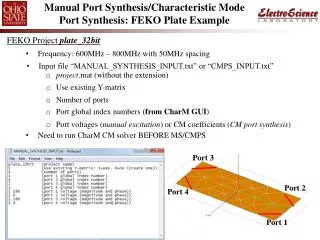
2.0” nominal CAD space clearance 0.36” to 0.44” distance to center of probe + 0.065” to + 0.145” reduced radial clearance See next slide PORT 8 15 mm probe Ø (0.59”)
Clamp metrology probe points 2.0” nominal CAD space clearance Clamp envelope Spool piece port 0.43” distance to center of probe which implies a clamp to port surface distance of 0.725” (.43 + .59/2) 15 mm probe Ø (0.59”)
0.22” to 0.38” distance to center of probe + 0.007” to - 0.085” radial clearance change 2.0” nominal CAD space clearance 2.0” nominal CAD space clearance PORT 10
0.12” to 0.16” distance to center of probe + 0.175” to + 0.135” clearance space increase 0.32” distance to center of probe - 0.025” clearance reduction PORT 4
1.23” distance to center of probe; 1.525” port to clamp surface clearance 2.0” nominal CAD space clearance 1.79” distance to center of probe 2.08” port to clamp clearance PORT 12 0.30” distance to center of probe We need to look at this clamp! - 0.005” clearance reduction