Download
1 / 16
400 likes | 1.32k Views
6. Programmable Logic Device - Programmable Array Logic (PAL) - Generic Array Logic (GAL). Tocci Chapter 11 (Memory Devices) Read section 11-10 Review questions of section 11-10 Chapter 12 (Applications of a PLD) Read section 12-1 to 12-3. Programmable Logic Device.

E N D
6. Programmable Logic Device- Programmable Array Logic (PAL)- Generic Array Logic (GAL) Tocci Chapter 11 (Memory Devices) Read section 11-10 Review questions of section 11-10 Chapter 12 (Applications of a PLD) Read section 12-1 to 12-3
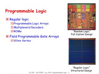
Programmable Logic Device • What is a Programmable Logic Device (PLD)? • an IC that contains large numbers of gates, flip-flops and registers that are interconnected on the chip • can be configured by the user to perform a logic function • many of the connections are fusible links that can be broken
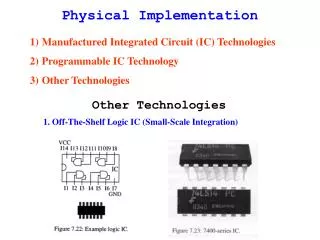
Programmable Logic Device • Problems of using standard ICs in logic design: • require hundreds or thousands of these ICs • require a considerable amount of circuit board space • require a great deal of time and cost in inserting, soldering, and testing • require to keep a significant inventory of ICs
Advantages of using PLDs • Advantages of reducing the no. of ICs using PLD: • less board space • fewer printed circuit boards • smaller enclosures • lower power requirements (i.e., smaller power supplies) • faster and less costly assembly processes • higher reliability (fewer ICs and circuit connections => easier troubleshooting) • availability of design software
Programmable Logic Device • Basic Ideas of PLD • A PLD consists of an array of AND gates and an array of OR gates • Each input feeds both a non-inverting buffer and an inverting buffer to produce the true and inverted forms of each variable. (i.e. the input lines to the AND-gate array) • The AND outputs are called the product lines • Each product line is connected to one of the inputs of each OR gate • Three fundamental types of standard PLDs: PROM, PAL, and PLA
PAL • Programmable Array Logic (PAL) • The input lines to the AND array are programmable and the output lines to the OR array are hard-wired • Simplify the logic function (e.g. using K-map) before putting design into PLA. K-maps
Programmable Logic Devices PROM PAL PLAInput lines hard-wired prog. prog.Output lines prog. hard-wired prog.Versatility low moderate highDifficulty in low moderate highmanufacturing, programming and testing
Generic Array Logic (GAL) • Instead of using one-time programmable fuse links, GAL use an EEPROM array. • Block diagram of GAL 16V8A See Fig. 12-1, P.775, Tocci • 8 dedicated input pins • 2 special function pins (CK, OE) • 8 pins that can be used as inputs or outputs
Output Structure in PLD • Output logic marcrocells of 16V8R
Output Structure in PLD • The macrocell can be individually configured to bypass the flip-flop. • The output can either be programmed to be registered (with flip-flop) or combinational (flip-flop bypassed). • The PLD can be programmed as sequential or combinational logic.
Practical Design of using PLD • Simple combinational logic implementation • Example 12-1 and Fig. 12-6, P.780, Tocci • Simple sequential logic implementation • Example 12-2 and Fig. 12-8, P.782-3, Tocci
Programming PLD • Equipment to design and build circuits using PLDs (Fig. 12-11, P.787) • personal computer • PLD development software • programming fixture • software to drive the programming fixture • PLD • JEDEC - a standard format for transferring programming data for PLDs (independent of PLD manufacturers or software)
Development Software • Allow users to enter their design in some convenient way • Automatically create a JEDEC file • Original software - PALASM (PAL assembler) • Powerful development software tools are referred as compiler. They can accept more abstract representation of same design and translate it into hardware details necessary to program the PLD. e.g. CUPL, ABEL • Some high-level compiler include schematic capture option allowing entry operation by drawing a logic circuit diagram • Logic compiler also allow to enter the design in the form of truth table or state table. Some even accept timing diagram as input.