Download
1 / 15
150 likes | 156 Views
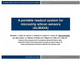
Status of the ALIBAVA system. 13th RD50 Workshop, 10-12 November 2008, CERN. Ricardo Marco-Hernández. IFIC(CSIC-Universidad de Valencia) 1. Status of the ALIBAVA system. Marco-Hernández, R. a , On behalf the ALIBAVA Collaboration b

E N D
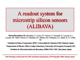
Status of the ALIBAVA system 13th RD50 Workshop, 10-12 November 2008, CERN Ricardo Marco-Hernández IFIC(CSIC-Universidad de Valencia) 1 Status of the ALIBAVA system Marco-Hernández, R.a, On behalf the ALIBAVA Collaboration b a Instituto de Física Corpuscular (IFIC), Universidad de Valencia-CSIC,Valencia, Spain. b Department of Physics, Oliver Lodge Laboratory, University of Liverpool, Liverpool, UK. Instituto de Microelectrónica de Barcelona, IMB-CNM, CSIC, Barcelona, Spain. Instituto de Física Corpuscular (IFIC), Universidad de Valencia-CSIC,Valencia, Spain.
Status of the ALIBAVA system 13th RD50 Workshop, 10-12 November 2008, CERN ALIBAVA Ricardo Marco-Hernández IFIC(CSIC-Universidad de Valencia) 2 Outline • Main system characteristics. • System architecture. • Daughter board. • Mother board. • PC software. • Processing of acquired data. • Measurements with non-irradiated detectors. • Measurements with irradiated detectors. • Data correction factors. • Production status. • Summary.
Status of the ALIBAVA system 13th RD50 Workshop, 10-12 November 2008, CERN Ricardo Marco-Hernández IFIC(CSIC-Universidad de Valencia) 3 Main system characteristics • A compact and portable system. • The system can be used with two different laboratory setups: • Radioactive source: external trigger input from one or two photomultipliers. • Laser system: synchronized trigger output generated internally for pulsing an external excitation source. • The system contains two front-end readout chips (Beetle chip used in LHCb) to acquire the detector signals. • USB communication with a PC which will store and will process the data acquired. • System control from a PC software application in communication with a FPGA which will interpret and will execute the orders. • Own supply system from AC mains. The main goal is reconstructing the analogue pulse shape from the readout chip front-end with the highest fidelity from the acquired data.
Status of the ALIBAVA system 13th RD50 Workshop, 10-12 November 2008, CERN Ricardo Marco-Hernández IFIC(CSIC-Universidad de Valencia) 4 System architecture • Software part (PC) and hardware part connected by USB. • Hardware part: a dual board based system connected by flat cable. • Mother board intended: • To process the analogue data that comes from the readout chips. • To process the trigger input signal in case of radioactive source setup or to generate a trigger signal if a laser setup is used. • To control the hardware part. • To communicate with a PC via USB. • Daughter board : • It is a small board. • It contains two Beetle readout chips • It has fan-ins and detector support to interface the sensors. • Software part: • It controls the whole system (configuration, calibration and acquisition). • It generates an output file for further data processing.
Status of the ALIBAVA system 13th RD50 Workshop, 10-12 November 2008, CERN Ricardo Marco-Hernández IFIC(CSIC-Universidad de Valencia) 5 Daughter board • Two Beetle readout chips in parallel mode. • 256 input channels. • Analogue front-end with 25 ns of peaking time. • Analogue multiplexed readout of each chip. • Output dynamic range ~ ±110000 electrons. • Buffer stage for sending the analogue output signals to the mother board. • Control signals provided by the mother board and shared by both Beetle chips. • A thermistor (NTC) for sensing the temperature close the Beetle chips. • Low voltage DC level (5 V) for Beetle chips (2.5 V) and buffer stage power supply (3 V): provided by the motherboard. • High voltage DC level for silicon detector(s) bias: external power supply. • Fan-ins and detector board: multiple wire bonding and two different sensor sizes.
Status of the ALIBAVA system 13th RD50 Workshop, 10-12 November 2008, CERN Ricardo Marco-Hernández IFIC(CSIC-Universidad de Valencia) 6 Mother board • Analogue signal conditioning: • Amplification and filtering: minimization of noise. • Buffering: two copies of the Beetle multiplexed analogue outputs for spying with a scope • ADC: digitalization at 40 MSps of the Beelte analogue multiplexed signals. • Digital converter: temperature analogue signal digitalization. • Generation of control signals for Beetle chips by FPGA: DAQ sequences and configuration. • Trigger conditioning and TDC for obtaining a time stamp of each trigger with radioactive source setup. • Generation of a trigger output with programmable delay for the laser source. • USB controller. • SDRAM (512 Mb) for temporal storage of acquired data. • FPGA (40 MHz): custom logic and embedded µP. • Control of the hardware. • Synchronization of DAQ sequences. • Generation of Beetle control signals. • Communication with the software. • Supply system: from AC/DC desktop power supply (5V). • Generation of MB and DB supply levels.
Status of the ALIBAVA system 13th RD50 Workshop, 10-12 November 2008, CERN Ricardo Marco-Hernández IFIC(CSIC-Universidad de Valencia) 7 PC software • Functions: • Control the whole system (configuration, calibration and acquisition). • Processing and monitoring of acquired data. • User interface with the system (GUI). • Generation of information (output files). • Two software levels: • Low level: • Software/mother board communication by USB: VCP (virtual com port) driver (2.4 Mb/s) used. • Processing of acquired data. • High level: • GUI: control of the system and data monitoring. • Output file generation for further processing and analysis. • Programmed in C++. • Operating system compatibility: • Linux version fully operational. • Maybe Windows in the future. • There are also macros for ROOT in order to process the data acquired with the software.
Status of the ALIBAVA system 13th RD50 Workshop, 10-12 November 2008, CERN Raw data (ADC counts vs channel number): digitalization of the Beetle analogue multiplexed output signal Raw data with pedestal value for each channel corrected (ADC counts vs channel number) Signal corresponding to an event (trigger): ADC counts vs channel number Common mode correction Ricardo Marco-Hernández IFIC(CSIC-Universidad de Valencia) 8 Processing of the aquired data Signal is computed as the sum of strips in a cluster. • Feed S/N > 6. • Neighbours S/N > 2.5. We can obtain different representations of acquired data from a given number of triggers. We use the calibration data for ADC counts to electrons conversion Pulse shape reconstruction: collected charge (electrons) vs. delay (ns) Signal computation of acquireddata from each trigger Pedestals correction Signal spectrum with a time cut: number of events vs. collected charge (electrons)
Status of the ALIBAVA system 13th RD50 Workshop, 10-12 November 2008, CERN Ricardo Marco-Hernández IFIC(CSIC-Universidad de Valencia) 9 Measurements non-irradiated detectors Figure 1 • Carried out with both non-irradiated P+N and N+Pdetectors. • At T = 20 ºC with both laser setup and radioactive source setup. • Calibration data is ok at T = 20 ºC: we calculate the ADC counts/electrons rate for each input channel (figure 1). • Measurements with β source (90Sr) as expected. • We can calculate the noise from the signal spectum (figure 2): σ~ 1200 electrons. • Also the charge corresponding to a mip from the signal spectrum with a time cut (figure 3): peak of the distribution 26940 electrons • SNR as mip charge divided by noise: ~ 22. • Measurements with laser setup as expected as well. • We can obtain the pulse shape reconstruction (figure 4 and figure 5). • Also the spectrum of the signal acquired. Figure 2 N+P detector Figure 3 N+P detector Figure 4 P+N detector Figure 5 N+P detector
Status of the ALIBAVA system 13th RD50 Workshop, 10-12 November 2008, CERN Ricardo Marco-Hernández IFIC(CSIC-Universidad de Valencia) 10 Measurements with irradiated detectors (I) • We have to operate the system inside a fridge (DB) @ -30 ºC. • Two effects on the Beetle chip front-end circuit: • Gain changes. • Calibration circuit becomes almost useless…
Status of the ALIBAVA system 13th RD50 Workshop, 10-12 November 2008, CERN Ricardo Marco-Hernández IFIC(CSIC-Universidad de Valencia) 11 Measurements with irradiated detectors (II) • We have to operate the system inside a fridge (DB) @ -30 ºC. • Two effects on the Beetle chip front-end circuit: • Gain changes. • Calibration circuit becomes almost useless… Use calibration at 20 ºC and Gain correction factor: Rcal = Qoutside/Qfridge
Status of the ALIBAVA system 13th RD50 Workshop, 10-12 November 2008, CERN Ricardo Marco-Hernández IFIC(CSIC-Universidad de Valencia) 12 Data correction factors • We measure on ADCs • We scan the voltages with laser and measure with β source for a few voltages (low activity source) • We compute Rsrc = Qsource/Qlaser • From the calibration we have Rcal (previous slide): gain correction factor and calibration data at room temperature. • We normalize so that the peak of the source in non-irradiated sensors is at 24000 electrons. • R24ke • All in all, for the laser data: Q = R24ke × Rcal × Rsrc × ADC Measurements of collected charge carried out with ALIBAVA system in Valencia. ATLAS07 sensors irradiated with neutrons presented by C. Lacasta in ATLAS Tracker Upgrade Workshop, NIIKHEF,November 2008.
Status of the ALIBAVA system 13th RD50 Workshop, 10-12 November 2008, CERN Ricardo Marco-Hernández IFIC(CSIC-Universidad de Valencia) 13 Production status • We are producing currently 20 ALIBAVA systems for the RD50 collaboration members. • We envisage to have these systems ready to distribute by December of 2008. • What are going to be included with each system? • MB and DB with their corresponding boxes. • Software (Linux version). • AC/DC desktop power supply. • USB cable and flat cable. • Two lemo connectors for the detectors power supply cable. • A number of fan-ins sets (to be determined). • A number of detector boards (to be determined). • Documentation for using the system. • How much are going to cost the system? • About 7k€. • We can produce more systems if required.
Status of the ALIBAVA system 13th RD50 Workshop, 10-12 November 2008, CERN Ricardo Marco-Hernández IFIC(CSIC-Universidad de Valencia) 14 Summary • The readout system has been developed and is fully operational. • The system can operate with different types and different sizes of microstrip detectors: • n-type. • p-type. • Irradiated and non-irradiated. • Up to 256 input channels. • Two flavours of detector boards to accommodate detectors of different sizes (1 cm2 or 3 cm2). • The system is designed to work with a radioactive source setup and laser setup: useful for comparing results with the same detector. • The system has been tested with laser setup and a β source: • It works correctly: already used for carrying out measurements with ATLAS 07 detectors. • With p-type and n-type detectors. • SNR is enough for irradiated and non-irradiated detectors. • Calibration factor must be calculated for measurements at low T (-30 ºC). • Data acquired with the system can be easily processed using ROOT framework: some macros already developed. • The system will be distributed among RD50 Collaboration members (currently under production). • Future work: • Upgrade of the system for testbeam acquisition by synchronizing various ALIBAVAs.
Status of the ALIBAVA system 13th RD50 Workshop, 10-12 November 2008, CERN Ricardo Marco-Hernández IFIC(CSIC-Universidad de Valencia) 15 Status of the ALIBAVA system Marco-Hernández, R.a, On behalf the ALIBAVA Collaboration b a Instituto de Física Corpuscular (IFIC), Universidad de Valencia-CSIC,Valencia, Spain. b Department of Physics, Oliver Lodge Laboratory, University of Liverpool, Liverpool, UK. Instituto de Microelectrónica de Barcelona, IMB-CNM, CSIC, Barcelona, Spain. Instituto de Física Corpuscular (IFIC), Universidad de Valencia-CSIC,Valencia, Spain.