Download
1 / 188
1.89k likes | 2.24k Views
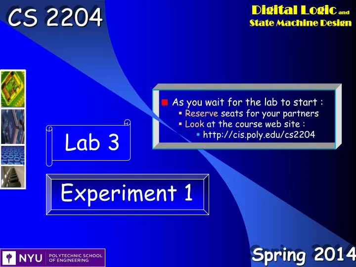
Experiment 1 Lab 3 Outline Presentation Using CS2204 Lab & Engineering Fundamentals Digital Design Trends Digital Design Tools Using Term Project (pages 8 – 13 and 16 - 20 ) The input/output relationship ≡ O peration ≡ Purpose ≡ Game rules

E N D
CS 2204 Spring 2014 • Experiment 1 Lab 3 Outline • Presentation • Using CS2204 Lab & Engineering Fundamentals • Digital Design Trends • Digital Design Tools • Using Term Project (pages 8 – 13 and 16 - 20) • The input/output relationship≡ Operation≡ Purpose ≡ Game rules • Term project operation diagram and initial partitionings • Analysis of Block 2 of the term project • Individual work • Experiment 1 is over three weeks : Labs 3, 4 and 5 • Develop a 4-bit 2-to-1 MUX of Block 2 • By using 1-bit 2-to-1 MUXes over three weeks • Today • Analyze (simulate) a 4-bit 2-to-1 MUX of Block 2 • Simulation of other components in ppm
Digital Design Trends • Current Digital Design Tools • Even if we use current digital engineering design techniques • Top-down, team-based and core-based design • Today’s circuits are too complex to be developed fast • One needs powerful tools to simplify the design process CS 2204 Spring 2014
Current Digital Engineering Design Tools • Computer aided design (CAD) software to develop circuits on computers • Computers handle the details • Field Programmable gate arrays (FPGAs) to physically test the chip designed • FPGAs are used when a new chip is developed • Complex circuits require more than one FPGA chip CS 2204 Spring 2014
CAD Software • Abstracts the design by hiding details unnecessary at the moment • Design editors • To design the circuit • Schematic and hardware description language (HDL) • Logic and timing simulators • To test the design • FPGA interfaces and downloaders • Chip layout editors • PCB layout editors CS 2204 Spring 2014
CS 2204 Spring 2014 • CAD Software • Polytechnic digital design software packages • Xilinx ISE , Mentor Graphics, Cadence, Synopsis • All industry software packages • Senior-level and graduate courses use them • Xilinx ISE 12.4 • Targets FPGA as the final product, not chips • Mentor Graphics, Cadence and Synopsis target chips and/or PCBs • We will use it to do schematic design, simulations and FPGAimplementations • Installed on PCs in 227RH
a b a c y(a, b, c) =a.b + a.c CS 2204 Spring 2014 • Digital Design • Schematic (traditional) • Circuit diagrams with gates, FFs and wires are drawn • Impractical if the component (gate + FF) count is high such as today’s microprocessors
Schematic Design • One schematic sheet containing many components and wires is prohibitive • Still impractical even if the schematic is partitioned to sheets • The designer has to deal with many unnecessary details • Drawing many wires and placing many components are some of the unnecessary details • CS2204 uses schematic design since the term project is not very complex CS 2204 Spring 2014
Digital Design • Hardware Description Language (HDL)-based design (now) • The designer writes a program in an HDL to design a digital circuit • CAD software converts text to components and wires • The HDL program has “modules” to allow block-based, team-based and core-based design • Today’s digital circuits require HDL-based design • Software languages, including graphical languages (C, C++, MATLAB, LabVIEW,…) will be used to design hardware (in thefuture) • C, C++, MATLAB and LabVIEW are increasingly used to design hardware today CS 2204 Spring 2014
Popular HDL Languages • VHDL : VHSIC HDL • VHSIC≡ Very High Speed Integrated Circuit • A project of DARPA (Defense Advanced Projects Agency) • Developed in the 1980s • Looks like the ADA language (of the 1980s) • Taught at Poly • Verilog HDL • Equally used with VHDL • Developed earlier than VHDL • Looks like the C language CS 2204 Spring 2014
Car Alarm Schematic engine AND alarm NOT belt alarm = engine belt • A VHDL Program Example libraryIEEE; useIEEE.std_logic_1164.all; entity caralarmis port( engine:inSTD_LOGIC; belt:inSTD_LOGIC; alarm:outSTD_LOGIC ); endcaralarm; architecturecaralarm_dataflowofcaralarmis begin alarm <= ‘1’whenengine = ‘1’andbelt = ‘0’ else‘0’ ; endcaralarm_dataflow ; CS 2204 Spring 2014
Car Alarm Schematic engine AND alarm NOT belt alarm = engine belt • A VHDL Program Example libraryIEEE; use IEEE.std_logic_1164.all; entitycaralarmis port( engine:in STD_LOGIC; belt:in STD_LOGIC; alarm:out STD_LOGIC ); endcaralarm; architecturecaralarm_dataflow ofcaralarmis begin alarm <= engineandnotbelt ; endcaralarm_dataflow ; CS 2204 Spring 2014
libraryIEEE; useIEEE.std_logic_1164.all entity fulladder is port (A, B, CIN : in STD_LOGIC; SUM, COUT : out STD_LOGIC); end fulladder; architecture fulladder_dataflow of fulladder is signal s1, s2, s3,s4,s5: STD_LOGIC; begin s1 <= A xor B; SUM <= s1 xor CIN; s2 <= A and B; s3 <= B and CIN; s4 <= A and CIN; s5 <= s2 or s3; COUT <= s4 or s5; end fulladder_dataflow; A COUT 1-bit Adder B SUM CIN • Another VHDL Program Example CS 2204 Spring 2014
VHDL at Poly • CS2204 covers VHDL during the last lecture of the semester • EE4313 (Computer Engineering Design Project I) is on VHDL • A number of EL (EE graduate) courses also cover VHDL CS 2204 Spring 2014
Field Programmable Gate Arrays (FPGAs) • FPGAs are used for prototyping of chips to test the design physically • They are used to develop a new chip • The newchip is tested on FPGAs • Complex circuits require more than one FPGA chip • Designers have a better understanding of their new chip • Design problems not discovered while simulating the circuit on computers are discovered ► Additional logic errors ► Speed, cost, power, size, etc. issues • FPGAs are now finding use in commercial products • Xilinx, Altera, Lattice Semiconductor, Microsemi, are some of the largest FPGA companies CS 2204 Spring 2014
FPGAs to Test the design physically • Why not fabricate the prototype chip after extensive simulations on computers ? • Not all logic errors and issues can be discovered via simulations • FPGAs at Poly • Some upper level EE and EL (graduate EE) courses require FPGAs • EL6493 Advances in Reconfigurable Systems CS 2204 Spring 2014
Xilinx FPGAs • An FPGA is hardware programmed (reconfigured) by downloading a bitfile to the FPGA • The bit file is generated from the schematic by the Xilinx ISE software • The internal circuitry consist of • Configurable (programmable) logic blocks (CLBs) • A CLB contains look-up tables (LUTs), flip-flops and other components • A look-up table implements a combinational circuit • Gates do NOT implement combinational circuits on the FPGA chip ! • Programmable connections • Other blocks CS 2204 Spring 2014
. . . CLB . . . . . . . . . . . . . . . . . . . . . • Xilinx FPGAs • Consist of configurable (programmable) logic blocks (CLBs), programmable connections and other blocks • A CLB contains look-up tables (LUTs), flip-flops and other components • A look-up table implements a combinational circuit CS 2204 Spring 2014
CS2204 Xilinx FPGA • Spartan-3E : XC3S500E-5FG320 • 1164 CLBs organized as a 46x34 array • Input/output blocks • Connecting the pins to the internal logic • Interfacing to the external world • 360 Kbit Block RAM • Embedded in the CLB array, replacing some of the CLBs • 20 18-bit multipliers • 4Digital clock manager blocks • Distributing and generating clock signals on the chip . . CLB . . . . . . . . . . . . . . . . . . . CS 2204 Spring 2014
CS2204 Xilinx FPGA • Spartan-3E : XC3S500E-5FG320 • A CLB • Implemented by means of fourslices • Contains eight LUTs and 8 FFs • Each LUT implements a 4-input 1-output combinational circuit • It contains 16 bits ! • There are also multiplexers, carry and arithmetic logic CLB CS 2204 Spring 2014
CS2204 Xilinx FPGA • Spartan-3E : XC3S500E-5FG320 • A CLB • Implemented by means of four slices • Contains eight LUTs and 8 FFs • Each slice has 2 LUTs and 2 D FFs • Right two slices in each CLB support only logic (SLICEL) • Left two slices in each CLB support both logic and memory functions (SLICEMEM) • The four LUTs in all the SLICEMEMs can be used to form a 74496-bit Distributed RAM CS 2204 Spring 2014
CS2204 Xilinx FPGA • Spartan-3E : XC3S500E-5FG320 • A CLB • Implemented by means of four slices • Contains eight LUTs and 8 FFs • Each slice has 2 LUTs and 2 D FFs • There are also multiplexers, carry and arithmetic logic • Each slice accepts cin and outputs cout through a number of AND gates • Each slice also outputs sum by using EXOR gates CS 2204 Spring 2014
CS2204 Xilinx FPGA • Spartan-3E : XC3S500E-5FG320 • 360 Kbit Block RAM • Embedded in the CLB array, replacing some of the CLBs • 2018Kbit dual ported Block RAMS on two columns replacing the CLBs there • 2018-bit multipliers • Each is immediately adjacent to a block RAM • Each is a 18x18 multiplier CS 2204 Spring 2014
CS2204 Xilinx FPGA • Spartan-3E : XC3S500E-5FG320 • 4Digital clock manager (DCM) blocks • Distributing and generatingclock signals on the chip • Clock-skew Elimination: Clock skew within a system occurs due to the different arrival times of a clock signal at different points on the chip, typically caused by the clock signal distribution network • Clock skew is undesirable in high frequency applications • The DCM eliminates clock skew by phase-aligning the output clock signal that it generates with the incoming clock signal • This mechanism effectively cancels out the clock distribution delays • Frequency Synthesis: The DCM can generate a wide range of different output clock frequencies derived from the incoming clock signal • This is accomplished by either multiplying and/or dividing the frequency of the input clock signal by any of several different factors • Phase Shifting: The DCM provides the ability to shift the phase of all its output clock signals with respect to the input clock signal • There are global clock lines to distribute clock signals with little delay CS 2204 Spring 2014
CS2204 Xilinx FPGA • Spartan-3E : XC3S500E-5FG320 • Consist of configurable (programmable) logic blocks (CLBs), programmable connections and other blocks • Interconnect, also called routing, is segmented for optimal connectivity • There are four kinds of interconnects: long lines, hex lines, double lines, and direct lines • The Xilinx Place and Route (PAR) software tries to use the interconnect array to deliver optimal system performance . . CLB . . . . . . . . . . . . . . . . . . . CS 2204 Spring 2014
Xilinx FPGAs • Spartan-3E : XC3S500E-5FG320 • There are 320 pins on the bottom of the FPGA chip CS 2204 Spring 2014
. . . . . . . . . . . . . . . . . . . . . . . . • Xilinx FPGAs • An FPGA is hardware programmed (reconfigured) by downloading a bit file to the FPGA • The bit file is generated from the schematic by the Xilinx Foundation software • Spartan-3E : XC3S500E-5FG320 • 1164 CLBs organized as a 46x34 array CS 2204 Spring 2014
. . . . . . . . . . . . . . . . . . . . . . . . • Xilinx FPGAs • An FPGA is hardware programmed (reconfigured) by downloading a bit file to the FPGA • The bit file is generated from the schematic by the Xilinx Foundation software • Spartan-3E : XC3S500E-5FG320 • 1164 CLBs organized as a 46x34 array CLB slice SLICEL CS 2204 Spring 2014
Xilinx FPGAs • An FPGA is hardware programmed (reconfigured) by downloading a bit file to the FPGA • The bit file is generated from the schematic by the Xilinx Foundation software • Spartan-3E : XC3S500E-5FG320 • 1164 CLBs organized as a 46x34 array What are they ? CS 2204 Spring 2014
Xilinx FPGAs • An FPGA is hardware programmed (reconfigured) by downloading a bit file to the FPGA • The bit file is generated from the schematic by the Xilinx Foundation software • Spartan-3E : XC3S500E-5FG320 • 1164 CLBs organized as a 46x34 array CS 2204 Spring 2014
Xilinx FPGAs • An FPGA is hardware programmed (reconfigured) by downloading a bit file to the FPGA • The bit file is generated from the schematic by the Xilinx Foundation software • Spartan-3E : XC3S500E-5FG320 • 1164 CLBs organized as a 46x34 array CS 2204 Spring 2014
The Term Project Usage of the XC3S500E-5FG320 282 out of 4656 slices used : 6% utilization CS 2204 Spring 2014
Analysis of the Term Project • The term projectblack-box view • The term projectoperation diagram • The term projectblack box partitioning CS 2204 Spring 2014
The Analysis of the Term Project • Polytechnic Playing Machine, Ppm • The term project is human vs. machine • There are twoother Ppm versions which are not term projects • Machine vs. machine • Human vs. human CS 2204 Spring 2014
The Term Project, Ppm • The black-box view • Ppm is sequential (not combinational) • A large number of FFs are used ! • We need to partition the Ppm based on major operations • We have to obtain the operation diagram From page 2 of the Term Project Handout CS 2204 Spring 2014
The Term Project, Ppm • The black-box view • From page 3 of the Term Project Handout CS 2204 Spring 2014
The term project, Ppm • The input/output devices of the Ppm (without clock) • From page 2 of the Term Project Handout Please be gentle with push buttons and switches CS 2204 Spring 2014
Sequential Circuit Basics • Today’s sequential circuit are synchronous, meaning that all operations start and end at the same time • This implies all operations take the same time • Add, subtract, compare, and, or, not, nand, nor,… • These operations are performed by combinational circuits • Combinational circuits are high speed circuits ! • Actually, some operations take less time than others • Addition and subtraction take the longest time • Comparing two 32-bit numbers takes much less time than adding two 32 bit numbers • We still wait as if we are doing an add or subtract ≡ We waste time • Our circuit would be faster if they were notsynchronous ≡asynchronous • If we used asynchronous sequential circuits, they would be faster • There is no clock ! • An asynchronous microprocessor ≡There is no clock ! • However, designing, testing, modifying and upgrading asynchronous sequential circuits are more difficult CS 2204 Spring 2014
Sequential Circuit Basics • Today’s sequential circuit are synchronous, meaning that all operations start and end at the same time • All operations take the same time • A special input, the clock input indicates when operations start and end • All operations take the same time ≡Oneclock period of time ! • All synchronous sequential circuits use a clock signal Clock Start now Start now All operations take this time ! End now One clock period End now CS 2204 Spring 2014
Sequential Circuit Basics • A special input, the clock input indicates when operations start and end • The clock period duration indicates the operation duration • The clock period duration is determined by the longest operation duration • The clock period duration is slightly longer than the longest operation duration to account for temperature and humidity changes and component variations • We check all operation duration lengths and determine which one takes the longest time and so adjust the clock period duration Clock Start now Start now Device tolerance time All operations take this time ! Max add time End now End now One clock period CS 2204 Spring 2014
Sequential Circuit Basics • A special input, the clock input indicates when operations start and end • The clock period duration indicates the operation duration • The clock period duration is specified in terms of seconds • The relationship between the clock period and clock frequency Clock Cp 1 Cp 2 Cp 3 Cp 4 Cp 5 Cp 6 Cp 7 Cp 8 CS 2204 Spring 2014
Sequential Circuit Basics • A special input, the clock input indicates when operations start and end • The clock period duration indicates the operation duration • The clock frequency is specified in terms of Hertz • One Hertz means there is one clock period in one second • Then, the clock period duration is 1 second • Operations take less than 1 second ! Clock Cp 1 Cp 2 Cp 3 Cp 4 Cp 5 Cp 6 Cp 7 Cp 8 1 second 1 second 1 second 1 second CS 2204 Spring 2014
Sequential Circuit Basics • A special input, the clock input indicates when operations start and end • The clock period duration indicates the operation duration • The clock frequency is specified in terms of Hertz • If the clock frequency is 1 GHz ? • 1 GHz ≡ 109 Hertz • Then, there are 1 billion clock periods in second ! • Then, the clock period duration is 1 ns • Operations take less than 1 nano second ≡ They take in terms of picoseconds ! Clock Cp 1 Cp 2 Cp 3 Cp 4 Cp 5 Cp 6 Cp 7 Cp 8 1 ns 1 ns 1 ns 1 ns CS 2204 Spring 2014
Sequential Circuit Basics • We indicate which operation takes place when by using a diagram that has circles and arrows • To show operations with respect to time • A circle specifies which set of operations take place in parallel • The circle is a state • In a particular clock period only one state happens • A state indicates which operations happen in parallel in the clock period that corresponds to a state • Arrows indicate which operations follows which operations • Arrows may be tagged with labels indicating conditions to satisfy to take them • The result is a high-level state diagram with microoperations ! Clock period 45 R K + M a a OUT = R Clock period 46 M M - 1 Time … … CS 2204 Spring 2014
Sequential Circuit Basics • When we start designing a complexsequential circuit, we would not specify all the details ≡Top-down design ! • We would not draw a high-level state diagram • We draw an abstract state diagram • We draw an operation diagram • We use words to specify operations • We use complex tags next to arrows • Eventually, we obtain the high-level state diagram Add K and M Clock period 45 a is nonzero ? a is zero ? Subtract 1 from M Output result Clock period 46 … Time … CS 2204 Spring 2014
Sequential Circuit Basics • When we start designing a complexsequential circuit, we would not specify all the details ≡Top-down design ! • We draw an operation diagram • The operation diagram indicates major operations ≡The input/output relationship ! • We partition the complex sequential circuit based on the major operations, the design goals and technology≡ Product goals • We use complex tags next to arrows • Eventually, we obtain the high-level state diagram with more details ! Add K and M Clock period 45 a is nonzero ? a is zero ? Subtract 1 from M Output result Clock period 46 … Time … CS 2204 Spring 2014
Designing the Ppm circuit • Ppm is complex sequential circuit • We must obtain its operation Diagram ! • First take This operation diagram is too abstract Reset mode We cannot obtain the major operations ! Press BTN3 4 times Press BTN3 after playing RD with an adjacency Player 1 mode Convert the simplified operation diagram to a (more detailed) operation diagram Press BTN2 to skip Press BTN2 after playing RD without an adjacency Press BTN2 after playing RD with an adjacency Player 2 mode Convert each circle to one or more circles (steps or states) Press BTN3 after playing RD without an adjacency CS 2204 Spring 2014
LD0-LD2 on the FPGA board show the current state Ppm Input/output relationship From page 8 of the Term Project Handout Ppm operation diagram CS 2204 Spring 2014
Machine play block Points Calculation block Human play block Input/Output Block Play check block Machine Play Block is also active states 2 and 5 Input/Output Block is active in every state CS 2204 Spring 2014
The Ppm Term Project Partitioning • We have observed the following major operations • Interfacing to the input/output devices • Handling human player’s play • Controlling display operations based on game rules • Calculating new player points • Determining the machine player play • Hint for general partitioning • If you cannot figure out major operations, partition one major operation at a time CS 2204 Spring 2014