Download
1 / 29
300 likes | 664 Views
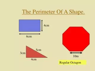
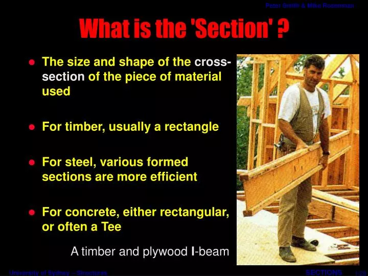
A timber and plywood I -beam. What is the 'Section' ?. The size and shape of the cross-section of the piece of material used For timber, usually a rectangle For steel, various formed sections are more efficient For concrete, either rectangular, or often a Tee. 1/28.

E N D
A timber and plywood I-beam What is the 'Section' ? • The size and shape of the cross-section of the piece of material used • For timber, usually a rectangle • For steel, various formed sections are more efficient • For concrete, either rectangular, or often a Tee 1/28
Some hot-rolled steel sections Why Different Shapes and Sizes • What shapes are possible in the material? • What shapes are efficient for the purpose? • Obviously, bigger is stronger, but less economical 2/28
Y X X Y Timber beam Cold-formed steel Timber post Hot-rolled steel Steel tube Which Way Around? • Beams are oriented one way • Depth around the X-axis is the strong way • Some lateral stiffness is also needed • Columns need to be stiff both ways (X and Y) 3/28
Unchanged length Most shortened Most lengthened Where Elasticity Comes in • ‘Stress is proportional to strain’ • Parts further from the centre strain more • The outer layers receive greatest stress 4/28
MR = Ca = Ta Internal Moment of Resistance The Section Fights Back • The stresses developed resist bending • Equilibrium happens when the resistance equals the applied bending moment All the compressive stresses add up to form a compressive force C C a T All the tensile stresses add up to form a tensile force T 5/28
b d 3 bd I = mm4 12 A Measure of Stiffness - I • Simple solutions for rectangular sections • Doing the maths (in the Notes) gives the Moment of Inertia For a rectangular section 6/28
A Measure of Stiffness - I (cont.) • The bigger the Moment of Inertia, the stiffer the section • It is also called Second Moment of Area • Contains d3, so depth is important • The bigger the Modulus of Elasticity of the material, the stiffer the section • Astiffer sectiondevelops itsMoment of Resistance withless curvature 7/28
b d 2 bd Z = mm3 6 A Measure of Strength - Z • Simple solutions for rectangular sections • Doing the maths (in the Notes) gives the Section Modulus For a rectangular section 8/28
A Measure of Strength - Z (cont.) • The bigger the Section Modulus, the stronger the section • Contains d2, so depth is important 9/28
depth is important Stiffness and Strength • Strength --> Failure of Element • Stiffness --> Amount of Deflection 10/28
A = bd Y b rx = d/√12 ry = b/√12 X X d Y Other Properties • The area tells how much stuff there is • used for columns and ties • directly affects weight and cost • The radius of gyration is a derivative of I • used in slenderness ratio 11/28
What about Non-Rectangles? • Can be calculated, with a little extra work • Manufacturers publish tables of properties 12/28
How do we Use these Properties? • Checking Beams • Designing Beams • given the beam section • check that thestresses & deflection are within the allowable limits • find the Bending Moment and Shear Force • select a suitable section 13/28
M is maximum here M f = Bending Moment Section Modulus Stress = Z How do we Use these Properties? (cont.) • Go back to the bending moment diagrams • Maximum stress occurs where bending moment is a maximum 14/28
b d < Actual Allowable? Using Z to Check the strength of a Beam • Given the beam size and material • Find the maximum Bending Moment • Use Stress = Moment/Section Modulus • Compare this stress to the Code allowable stress M = max BM Z = bd2 / 6 Actual Stress = M / Z Allowable Stress (from Code) 15/28
50 250 4 kNm Strength Checking Example • Given a softwood timber beam 250 x 50mm • Given maximum Bending Moment = 4kNm • Given Code allowable stress = 8MPa Section Modulus Z = bd2 / 6 = 50 x 2502 / 6 = 0.52 x 106 mm3 Actual Stressf= M / Z = 4 x 103 x 103 / 0.52 x 106 = 7.69 MPa < 8MPa Actual Stress < Allowable Stress 16/28
b? d? Using Z to design a Beam for Strength • Given the maximum Bending Moment • Given the Code allowable stress for the material • Use Section Modulus = Moment / Stress • Look up a table to find a suitable section M = max BM Allowable Stress (from Code) required Z = M / Allowable Stress a) choose b and d to giveZ >= than required Zor b) look up Tables of Properties 17/28
b? d? Strength Designing Example • Given the maximum Bending Moment = 4 kNm • Given the Code allowable stress for structural steel = 165 MPa required Z = 4 x 10⁶ / 165 =24 x 103mm3 (steel handbooks give Z values in 103mm3) looking up a catalogue of steel purlins we find C15020- C-section 150 deep, 2.0mm thickness has a Z = 27.89 x 103 mm3 (smallest section Z >= reqd Z) 18/28
W Depth, d Span, L What Controls Deflection? • Both E and I come into the deflection formula (Material and Section properties) • The load, W, and span, L3 • Note that I has a d3 factor • Span-to-depth ratios (L/d) are often used as a guide 19/28
W Central point load 3 WL 8d ¶ = L 48 EI Total load = W Uniformly Distributed Load (w per metre length) 3 5 WL 5d ¶ = L 384 EI whereWis the TOTALload Deflection Formulas - Simple Beams 20/28
Central point load W 3 WL 128d ¶ = L 3 EI Total load = W Uniformly Distributed Load (w per metre length) 3 WL 48d ¶ = L 8 EI whereWis theTOTALload Deflection Formulas - Cantilevers 21/28
Uniformly Distributed Load Total load = W (w per metre length) d L 3 whereWis theTOTALload WL ¶ = 384 EI Deflection Formula - Built-in Beams • The deflection is only one-fifth of a simply supported beam • Continuous beams are generally stiffer than simply supported beam 22/28
Given load,W, and span,L Given Modulus of Elasticity,E,and Moment of Inertia,I Use deflection formula to find deflection Be careful with units (work in N and mm) Compare to Code limit (usually given as L/500, L/250 etc) Using I to Check the Stiffness of a Beam • Given the beam size and material • Given the loading conditions • Use formula for maximum deflection • Compare this deflection to the Code allowable deflection 23/28
W = 8kN L = 4m Loading Diagram deflects too much - need to chose stiffer section Deflection Checking Example • Check the deflection of the steel channel previously designed for strength • The maximum deflection <= L / 500 I = 2.119 x 106 mm4 Section = C15020 E = 200 000 MPa d= (5/384) x WL3/EI mm ( Let us work in N and mm ) d= (5/384) x 8000 x 40003 / (200000 x 2.119 x 106) = 16 mm = 8 mm Maximum allowable deflection= 4000 / 500 24/28
65 150 75 200 design for strength check for deflection Deflection Checking Example (cont.) • Need twice as muchI • Could use same section back to back 100% more material • A channel C20020 (200 deep 2mm thick) has twice theIbut only 27% more material strategyfor heavily loaded beams 25/28
Given load,W, span,L, and Modulus of Elasticity, E Use the Code limit — e.g., turn L/500 into millimetres Use deflection formula to find minimum value ofI Look up tables or useI= bd3/12and choose b and d Using I to Design a Beam for Stiffness • Given the loading conditions • Given the Code allowable deflection • Use deflection formula to find I • Look up a table to find a suitable section 26/28
What Section to Use? = better sections for beams • Beams need largeIandZin direction of bending • Need stiffness in other direction to resist lateral buckling • Columns usually need large value ofr in both directions • Some sections useful for both 27/28
What Else can go Wrong? • Deep beams are economical but subject to lateral buckling 28/28