Download
1 / 27
270 likes | 485 Views
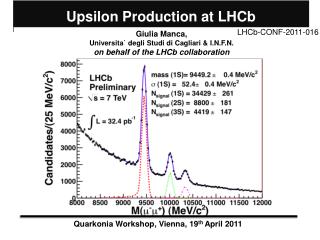
2nd International Symposium “ LHC Physics and Detectors” JINR Dubna, 28-30 June 2000. The LHCb Muon System Burkhard Schmidt / CERN on behalf of the LHCb collaboration LHCb Muon Group: Cagliari, CERN, Ferrara, Frascati, Marseille, PNPI, Potenza, Roma ‘La Sapienza’, Roma ‘Tor Vergata’, UFRJ.

E N D
2nd International Symposium “LHC Physics and Detectors”JINR Dubna, 28-30 June 2000 The LHCb Muon System Burkhard Schmidt / CERNon behalf of the LHCb collaboration LHCb Muon Group: Cagliari, CERN, Ferrara, Frascati, Marseille, PNPI, Potenza, Roma ‘La Sapienza’, Roma ‘Tor Vergata’, UFRJ
Outline: Introduction Physics Goals and Requirements Background Conditions Overview of the Muon System Detector Layout Detector Technologies Performance Studies FE-electronics FE-chip Electronics Architecure Planning and Conclusions LHCb Muon System B. Schmidt / CERN
Physics Goals: The Muon system of LHCb is primarily used as an identifier- and trigger system for muons produced in the decay of B-mesons: B X ; In particular:Bd J/(+-) Ks ; Bs J/(+-) ; Bs +- The muon momentum is measured precisely in the tracking system; the muon chambers are used to validate the muon candidate and match it with the track of the tracking system. Requirements: Modest momentum resolution (~25%) for a robust PT -selective trigger Good time resolution (few ns) for reliable bunch-crossing identification Good muon identification Introduction B. Schmidt / CERN
Background sources in the LHC environment: Primary background: - hadron punch-through including muons generated in the hadron shower - ,K X decays Radiation background: Photon “gas” generated via n- processesby hadrons interacting in the absorber Machine background: Energetic muons produced in beam-gas interactions and in machine elements upstream of the experimental area Requirements: High rate capability of chambers and good ageing properties of detector components System layout of sufficient granularity to provide a redundant muon trigger. Introduction B. Schmidt / CERN
Overview • 5 Muon stations with • 2 layers/station • 870m2 of detector area • arranged in ~1500 chambers • Hadron Absorber of 21 • thickness M1 M2 M3 M4 M5 • Stations M1 and M2 are used for the PT-measurement • Stations M2, M3 (trigger seed), M4 and M5 for muon track finding B. Schmidt / CERN
TP-Layout Optimized Layout Muon Detector Layout Station 1 B. Schmidt / CERN
Optimized Layout: Stations are subdivided in 4 regions with different pad size -> Region- and Pad-sizes scale by factor 2 Pad dimensions scale with station number -> Projectivity to interaction point Physical pads in stations M2-M5 are grouped to logical strips Due to the high occupancy in M1 strips are not possible. -> Significant reduction of channel number: Total number of physical channels: ~150 k (TP: ~240k) Total number of logical channels: ~ 26k (TP: ~45k) Required resolution in the bending plane leads to an x/y aspect ratio of 1/4 in stations M2 and M3 and 1/2 in M1 Muon Detector Layout B. Schmidt / CERN
Particle Rates in the Muon System • Applied Procedure: • LHCb peak Luminosity of 51032 cm2/shas been assumed • Estimation based on MARS as simulation package • Safety factor of 2.5 has been applied for M2-M5 and 2 for M1 dN/dA /cm2/int Required Rate Capability Three areas can be distinguished: I) Rate 100 KHz II) 100 kHz Rate 1KhzIII) Rate 1kHz B. Schmidt / CERN
Technology Choice: In the outer part of M4 and M5 a technology with moderate rate capability can be used -> RPC covers 48% of muon system For most of the regions MWPC with anode wire and/or cathode pad readoutare the optimal solution covers 52% of the total area No technology has been chosen yet for the inner part of station 1 integrated charge in 108s in a MWPC would be ~ 2-5 C/cm area size corresponds to < 1% of total muon system Muon System Technologies B. Schmidt / CERN
Characteristics: Provides excellent timing (time resolution < 2ns) Robust and flexible: electrodes and detector are independent several configurations possible (single-, double-gap) Cheap and simple to construct -> Produced in Industry Requirements: Rate capability: 1.2 kHz/cm2 -> Avalanche mode operation with C2H2F4/C4H10/SF6 95/4/1 gas mixture -> Use low-resistive Bakelite ( < 1010 Ohm cm ) Redundant spatial efficiency: > 99% / station -> Use two gaps (DRPC or OR-ed SRPC) Average cluster size < 1.2 strips (M3) and < 2 strips in M4/M5 Max. radiation dose (10 y) 100 Gy Activities: Carried out by Firenze and Roma ‘Tor Vergata’ groups RPC Detector: Overview B. Schmidt / CERN
RPC Detector: Layout • Schematic Layout for Regions 3+4: • 1 chamber: 2 gas gaps (2 SRPC with independent FE-chips or DRPC) • Each electrode measures space points (no x-y coincidence required!) 140-150cm split strips in region 3 with 96-192 strips/chamber 29-31cm • Total region 3 : • 48 chambers/station • 4.6k-9.2k FE-ch./station • Total region 4 : • 96-192 chambers/station • 9.2k FE-ch./station B. Schmidt / CERN
Results from tests at the CERN PS: Time resolution ~1.3 ns Full efficiency within 10 ns time window RPC Detector: Performance B. Schmidt / CERN
RPC Detector: Cluster Size • Contributions to the Cluster Size: • direct induction • -> geometrical effect, largest between strips • cross-talk SRPC • -> depends on electrical characteristics • of strip planes • Scan over adjacent strips DRPC (strips less shielded) B. Schmidt / CERN
RPC Detector: Performance • Cluster Size Studies: • Cluster size decreases with increasing threshold • At a given efficiencyOR of two SRPC allows • lower cluster size SRPC Two SRPC in OR B. Schmidt / CERN
Results from GIF-Tests: GIF Photon rate: R= 740 GBq 0.85(BR) 0.5/Att. 1/4r2 Procedure: Determine Rfrom measured plateau curve with photons R = 3.1 (1/Att)0.76 kHz/cm2 Calculate photon sensitivity factor ~1/800 RPC Detector: Rate Capability B. Schmidt / CERN
Results from tests at GIF: Gamma Irradiation Facility allows to test muon chambers under conditions comparable to those expected at the LHC. Test of 3 SRPC with x and y planes -> Efficiencies of >95% have been obtained at 1.8 KHz/cm2 -> RPC of low resistive material show good rate capability behavior RPC Detector: Rate Capability x-planes y-planes B. Schmidt / CERN
Characteristics: MWPC with anode and/or cathode readout are very well known Integrated charge in 10 LHC years (108s) is <1 C/cm in all regions considered MWPC operated with Ar/CO2/CF4 40/50/10 mixture has good aging properties Requirements: Efficiency within 20 ns time window: > 95% -> Two gaps, staggered, 1.5mm wire spacing Redundant spatial efficiency: > 99% /station -> Two independent double gap chambers Activities: Carried out by PNPI (proponent), CERN, Firenze, Ferrara, Roma I (Potenza) and UFRJ groups MWPC Detector: Overview B. Schmidt / CERN
Chamber arrangement: Frontview Sideview Muon Detector Layout B. Schmidt / CERN
Timing Properties: time distribution Time resolution <3ns at operating point MWPC : Performance B. Schmidt / CERN
MWPC test at CERN PS: Gas Mixture: Ar/CO2/CF4 40/50/10 FE-electronics: Custom made (SMD) peaking time ~10ns -> Efficiency >99% within 20ns time window -> Dark count rate below < 50Hz/pad -> plateau length: ~ 400V for WPC ~ 300V for CPC MWPC: Performance B. Schmidt / CERN
High rate performance: FE-chip: ASDQ (has baseline restoration) MWPC: Performance -> Efficiency > 98% within 20ns time window ->No deterioration of timing properties B. Schmidt / CERN
FE-chip specifications: Peaking time ~10ns Rin: < 50 Cdet: 10-250pF Polarities: +/- Rate: up to 1MHz Dead time: < 50ns Dose: up to 1Mrad Sensitivity: ~10mV/fC (@Cdet =0) Low noise . . . ( Less stringent requirements for RPC FE-chip) -> Try to find existing chip satisfying our requirements FE - Electronics Inefficiency due to ASD pulse-width B. Schmidt / CERN
FE-chip candidates: MWPC: PNPI SMD (only for prototype studies) SONY ASD (Tested, radiation limit ~ 50krad, dead time ~90ns) ASDQ (Rin = 280, requires slight modification.) -> Performs in general very well MINSK ASD (matches well specifications, to be tested) CMP 16(for anode readout of CMS-EMU-chambers, to be tested) GaAs (to be tested) CARIOCA (0.25 CMOS) (under development) RPC: GaAs (0.6 MFET) (ATLAS RPC chip, very fast, radiation hard) -> Baseline option Bari (0.8 BiCMOS) (CMS RPC chip) FE - Electronics B. Schmidt / CERN
Status: Basic concept of the FE-Architecture has been developed Data reduction from physical channels (~150k ) to logical channels (~26k) done in intermediate boards Synchronization of data from the various stations (timing alignment of signals) with muons using a 3-bit TDC -> (ASD-chip) -> digital signals (~6m) -> channel reduction, FE-control (~4m) -> Synchronization, Pipelines, Trigger interface FE-Architecture FE-boards Intermediate boards Off Detector boards B. Schmidt / CERN
Baseline Locations for FE-Electronics: FE-boards with kind of ASD chip on the chambers Intermediate boards on the sides of each station Off detector Boards performing synchronization, Data Format+BC Id, LO-Pipeline and L1-Buffer on the sides of each station L0-Muon-Trigger-Electronics on the sides of station 3 FE-Electronics Locations B. Schmidt / CERN
Schedule: Decision on optimized muon detector layout Jan. 2000 Choice of detector technologies Feb/May 2000 Finalization of chamber design End 2000 Baseline choice of FE-chip End 2000 Technical Design Report (TDR) Early 2001 Preparation of Production lines 2001 Construction and test of muon chambers 2002-2003 Installation and commissioning of the muon system 2004 Project Plan B. Schmidt / CERN
Layout and Architecture: Optimized layout has been found, requiring less physical and logical channels Realistic data flow between chambers and the Trigger/DAQ System Detector Technologies: RPC: - Rate capability of ~ 3 kHz/cm2has been obtained - Time resolution of 1.3 ns with efficiency >99% in 10 ns time window MWPC: - Chambers perform very well up to rates > 100 kHz/cm2 - Time resolution < 3 ns with efficiency > 99% in 20 ns time window - Good ageing properties for Ar/CO2/CF4 (local tests > 13C/cm) Muon System is proceeding well towards the Technical Design Report Conclusions B. Schmidt / CERN