Download
1 / 22
220 likes | 353 Views
Seismically Enhanced Non-Structural Partition Walls for Unibody Residential Construction. Gregory Deierlein (PI) Eduardo Miranda (Co-PI) Scott Swensen Stanford University. Benjamin Fell (Co-PI) Amy Hopkins California State University, Sacramento. Quake Summit 2012

E N D
Seismically Enhanced Non-Structural Partition Walls for Unibody Residential Construction Gregory Deierlein (PI) Eduardo Miranda (Co-PI) Scott Swensen Stanford University Benjamin Fell (Co-PI) Amy Hopkins California State University, Sacramento Quake Summit 2012 The George E. Brown Network for Earthquake Engineering Simulation (NEES) July 12th, 2012
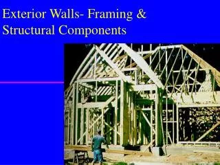
Introduction Traditional light-weight framed structures: • provide a high degree of life safety • are vulnerable to costly earthquake damage • About $20 billion in losses occurred to light-frame residential structures during the Northridge Earthquake • can lead to many displaced persons when damaged • The 1994 Northridge Earthquake destroyed or heavily damaged 60,000 housing units www.impactlab.net/wp-content/uplopads/2010/03/fiolmore-house.jpg
V VDBE R = 2 VR = 2 R = 6.5 VR = 6.5 DBE, 6.5 DBE, 2 Conventional Light-Frame Construction Current design methodology: • Design structural walls (i.e. plywood or OSB) to resist entire design lateral loads • Add architectural finishes such as gypsum partitions and stucco cladding, neglecting or heavily discounting lateral resistance R = 6.5 R = 2 Created by E. Miranda www.nhmodularhomes.com/house_cut_away.htm
Conventional Light-Frame Construction This design approach creates problems because in light framed construction, the ultimate load is achieved at large and damaging drifts peak lateral strength ≈ 2% drift onset of damage ≈ 0.2% drift www.flickr.com/photos/encouragement/3566839185
Opportunities to Improve Light-Frame Construction Alternate design methodology: • Design structural and architectural building components to work together in a ‘unibody’ manner to resist earthquake loads and deformations This method is economical because finishes wouldn’t have to be added, they just must be better integrated into the structural system majesticspeed.com/wp-content/uploads/2010/12/Car-Unibody.jpg www.imperialclub.com/Yr/1966/SpottersGuide/index.htm
Opportunities to Improve Light-Frame Construction This approach makes sense for light-framed buildings because: • low-rise framed structures are light • wall area is plentiful – increased strength is inexpensive • structural and architectural components are integral • most components are drift sensitive • for short period buildings, drifts are especially sensitive to lateral strength and stiffness Ruiz-Garcia and Miranda 2003
Unibody Design Concept • Design spectrum for Los Angeles, site class D, 5% damping Conventional Framed Building R = 6.5 Ω = 3 CR ≈ 1.6 (FEMA 440) Enhanced Framed Building R = 1 Ω = 1 CR ≈ 1 R/Ω CR
Research Objectives • Develop improved limited ductility light-frame design concepts which increase lateral structural strength and stiffness in an economical manner • Create and verify computational models that evaluate the seismic performance of enhanced ‘unibody’ systems • Formulate design methods and tools that consider (1) life safety and (2) life cycle costs and loss of building functionality during seismic events • Develop cost-effective base isolation systems for low-rise light framed structures in areas of high seismic hazard
Components of Light-framed Walls • Conventional mechanical fasteners • Novel mechanical fasteners (Maxiscrew by Ben Schmid) • Adhesive fastening systems Sheathing-to-framing Fastener Edge Panel Joint Finished Wall Flat Panel Joint
Mechanical Fastener Tests – ⅝” Type X GWB Monotonic Backbone +16% Δ = 1.3 mm (0.05”) Δ = 5.2 mm (0.20”) Δ = 10 mm (0.40”) Δ = 2.2 mm (0.09”) Δ = 25 mm (1.00”) Δ = 3.2 mm (0.13”)
Adhesive Gypsum-to-Wood Connections Monotonic Backbone +4.9x +5.5x
Adhesive Gypsum-to-Steel Connections Monotonic Backbone +2.9x +4.7x
Components of Light-frame Residential Structures • Conventional wall with coarse threaded screws • Wall with enhanced mechanical fasters • Wall with adhesive fastening and enhanced screws Sheathing-to-framing Fastener Edge Panel Joint Finished Wall Finished Wall Flat Panel Joint
Gypsum Sheathed Wall Tests – Wood Framing • Cyclic loading of 1.22 m (4 ft) square walls Coarse Threaded Screws Enhanced Fasteners Adhesive + Screws
Gypsum Sheathed Wall Tests – Wood Framing Cyclic Skeleton +4.2x +90% SDR = 0.21% SDR = 0.94% IBC/SDPWS Value (LRFD) + SDR = 2.0% SDR = 0.42% SDR = 0.63%
Gypsum Sheathed Wall Tests – Steel Framing Cyclic Skeleton +
Ongoing Testing of Gypsum and Stucco Clad Walls • Cyclic loading of 2.44m (8 ft) tall walls is currently being carried out. • Testing variables include: • sheathing(gypsum & stucco) and framing (wood and steel) material • use of adhesives • wall perforations and geometry • presence and configuration of end returns • configuration of holdowns and anchorages
Finite Element Wall Analysis Fit hysteretic model to component behavior for fasteners, adhesive, panel joints, and holdowns Individual fasteners Build framing and sheathing. Use modeled components to connect elements Panel joint Holdowns and anchorages
Finite Element Wall Analysis 4’ x 4’ wall, Adhesive + screws Cyclic Skeleton Curves
Current and Future Work Larger wall and room assembly tests to investigate the effect of: • wall-diaphragm interfaces • intersecting wall joints • window and door openings • anchorages and holdown variations • bi-directional loading The results from these tests will inform a full-scale building shake table test performed at the University of California, San Diego
Current and Future Work Computational simulations of: • sheathing-to-framing fasteners, hold downs, and panel joints • wall and wall assemblies • full building systems Create a new design methodology that considers limit states of (a) collapse safety and (b) damage control. Consider: • life cycle costs, including savings from earthquake insurance • potential deterioration caused by moisture, temperature fluctuation, aging, etc. SDR > 0.2% T = 0.2 s. R/ Ω = 2.17 T = 0.15 s. R/ Ω = 1 Porter., K. et al. (2011). “The ShakeOut Scenario: A hypothetical Mw7.8 earthquake on the southern San Andreas Fault.” Earthquake Spectra, Vol. 27, No. 2, pp. 239-261.
Acknowledgements • This research is funded by the National Science Foundation under a grant from the Network for Earthquake Engineering Simulation (CMMI – 1135029). • Additional support for testing was provided by the John A. Blume Earthquake Engineering Center at Stanford University. • Input and guidance from an advisory committee (Greg Luth, David Mar, Kelly Cobeen, Reynaud Serrette, John Osteraas, Rene Vignos, Geoff Bomba, and Ali Roufegarinejad) has been critical in the development of testing plans. • Support and encouragement from Ben Schmid, developer of the MAXI-SYSTEM and the enhanced fasteners tested is thankfully acknowledged.