Download
1 / 22
220 likes | 223 Views
Learn about the features, benefits, and applications of the CAN protocol in embedded systems. Discover how CAN ensures high reliability, data integrity, and flexibility in distributed real-time tasks.

E N D
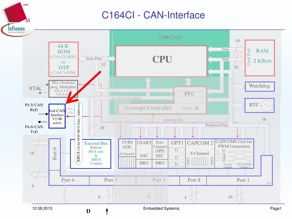
C164CI - CAN-Interface C166-Core 16 64 K ROM (C164 CI-8RM) or OTP (C164CI-8EM) Data RAM CPU Dual Port Instr./Data Data 2 KByte 32 16 PLL-Oscillator prog. Multiplier: 0.5; 1; 1.5; 2; 2.5; 3; 4; 5 Watchdog PEC External Instr./Data 13 ext. IR RTC P4.5/ CAN RxD Interrupt Controller Full-CAN Interface V2.0B active 16 Interrupt Bus Peripheral Data 16 P4.6/ CAN TxD XBUS (16-bit NON MUX Data / Addresses) 10-Bit ADC CAPCOM6 Unit for PWM Generation GPT1 Sync. Channel CAPCOM 2 USART External Bus 8/16 bit MUX only & XBUS Control T2 (SPI) Port 0 16 8-Channel 8-Channels ASC SSC Timer 13 T3 Timer 8 Timer 7 BRG BRG T4 1 Comp. Channel 3/6 CAPCOM Channels Port 3 Port 4 Port 5 Port 8 Port 1 6 8 9 16 4 Embedded Systems
Controller Area Network - CAN • CAN is a protocol for serial communication that supplies distributed realtime tasks with very high safety-requirements • CAN is standardized • ISO-DIS 11898 (high speed applications) • ISO-DIS 11519-2 (low speed applications) Embedded Systems
CAN - features • Low costs • Serial BUS for 2-wire-lines • High number of CAN-nodes in the automotive sector and in industrial electronics • Reliability/Data Integrity • Sophisticated mechanisms for error detection and handling result in high reliability of the transmissionExample: • 500 kbit/s, 25% bus-load, 2000 operating hours a yearResult: Only one undetected error in 1000 years! • Defective messages are detected and repeated • Every bus-node will be informed in case of an error • Low susceptibility against electromagnetic interference • Flexibility • Nodes can be very easily added or removed (plug & play). • The number of nodes isn’t limited by the protocol Embedded Systems
CAN - Features • High performance realtime-behaviour • Short messages: 0 to 8 bytes data per message. • Short time of latency between the request of a message and the start of the transmission • Prioritization of messages (Arbitration on Message Priority - AMP) • Multi Master protocol with CSMA/CD • High performance transmission rate • maximum transfer rate is 1 MBit/s at 40m bus-length and still about 40 kBit/s at bus-length of 1000m • Multi-Master-Operations • Every node can be the master • The bus-communication is not prevented by defective nodes • Defective nodes switch off from the bus by themselves • Flexible addressing mechanisms • Messages can be sent to only one or to several nodes • All modes receive simultaneously public data simultaneously Embedded Systems
CAN: Typical application Embedded Systems
CAL, CANopen (CiA) DeviceNet SDS (Honeywell) etc ... CAN (ISO 11898) Bosch Protocol layers of the CAN Process-Application Layer Application Layer 7 Logical Link Control Error detection, error handling; Control of data-flow; Acceptance filtering. Data Link Layer 2 Medium Access Control Bit-Stuffing, Framing, Arbitration Management Physical Signalling (Bit –coding, -timing, -synchron.) Physical Layer 1 Physical Medium Attachment (Transmitter/Receiver-Spec.) Medium Dependent Interface (Cable, Plug...) Embedded Systems
Higher Protocol Layers • CAN Application Layer (CAL) • Layer-7 Standard defined by “CAN in Automation” (CiA) • Network-Management for initialisation, monitoring and configuration of nodes in standardised form • Takes into account all aspects for the realisation of open communication via CAN (provides the cooperation of producer specific systems) • Available implementations of CAL simplify the user getting sophisticated “Controller Area Networks” • CANopen • Applications are based on CAL. • CANopen dertermines the mode of communication, an application- profile defines the meaning of certain messages) for the considered application • aim: Changeabilty of the subsystems of dedicated applications • Further higher protocol layers (standards): • Automotive-sector: VOLCANO, OSEK • Industrial Automation: DeviceNet (ODVA), SDS (Honeywell) Embedded Systems
CAL, CANopen (CiA) DeviceNet SDS (Honeywell) etc ... CAN (ISO 11898) Bosch CAN Protocol Layers Process-Application Layer Application Layer 7 Medium Access Control Bit-Stuffing, Framing, Arbitration Data Link Layer 2 Logical Link Control Error detection, error handling; Control of data-flow; Acceptance filtering. Management Physical Signalling (Bit –coding, -timing, -synchron.) Physical Layer 1 Physical Medium Attachment (Transmitter/Receiver-Spec.) Medium Dependent Interface (Cable, Plug...) Embedded Systems
Basic Characteristics of CAN • Asynchronous serial bus with linear bus-structure and identical nodes (Multi-Master-BUS) • Nodes won’t be addressed - the addresses are parts of the message and are related to those, just as the priority is a characteristic of the message • Two bus-states: dominant and recessive • the bus-activation is realized according to the "Wired-AND”-mechanism:dominant bits (logical 0) overwrite recessive bits (logical 1) • Bus-access via CSMA/CD with NDA (Carrier Sense Multiple Access/ Collision Detection with Non-Destructive Arbitration): • Before transmission it is tested whether the bus is free • Each sender tests whether the bus level is consistent to its transmission level • In case of discrepancy transmission is stopped and switched to receiving mode Embedded Systems
Basic Characteristics of CAN recessive NODE A dominant recessive NODE B dominant bus idle recessive CAN BUS dominant Node B transmits recessive levelbut reads back dominant level Node B loses arbitrationand switches to receive mode Embedded Systems
Typical Structure of CAN-Nodes Node A Node B z.B. ABS z.B. EMS Application z.B. 80C166 z.B. C164CR oder C515C Host-Controller (further nodes) z.B. SAE81C90 CAN-Controller CAN CAN-Transceiver CAN_H CAN-BUS UDiff CAN_L Embedded Systems
Identifier Data Field (0..8 Bytes) CRC-Field CAN data frames • There are two situations in communication: • One node is transmitting (’talker’), all other nodes are receiving (’listener’) • Nodes A requires (from an other node) anything and gets the answer • In ’Talk’-mode CAN-nodes use data frames • data frames consist of: • an identifier • the data, which should be transmitted • and a CRC-checksum • The Identifier specifies the content of the message (‘car velocity’ , ‘oil temperature’, etc.) and the priority of the message • The data field contains the appropriate value (’36 m/s’, ’110°C’, etc.). • The Cyclic Redundancy Check provides detection of transmission errors • All nodes receive the data frames, unaffected nodes ignore it Base Can Frame Embedded Systems
Identifier CRC-Field How hot is the oil ? Node B (oil temp.- Sensor) Remote Frame; Identifier ’Oil_temp' ~~~~~ ~~~~~ Node A 115°C 115 °C ! Data Frame; Identifier ’Oil_temp'; Contains required information CAN Remote Frames • In order to get information “Remote Frames” are used • A Remote Frame consists of the identifier and the CRC-checksum, no data are contained • The identifier refers to the information to be queried (’car velocity ', ’oil temperature', etc.) and the priority of the message • Every node having available the required information (e.g. the sensor for the oil temperature) reacts with transmission of the appropriate ‘Data Frame’ (same identifier, the data field contains the required information). Embedded Systems
Standard CAN / Extended CAN • CAN Version 2.0A - Standard CAN: • The Standard-Frame contains an 11 Bit identifier • With that 211 (=2048) different “messages” can be addressed • CAN Version 2.0B (active) - Extended CAN: • The “Extended Frame” has got an identifier with a length of 29 Bit • Via that more than 536 Million (229) different “messages” can be addressed • CAN Version 2.0B (passive) : • Some Standard-CAN-Nodes are not able to receive “Extended Frames”, but they are tolerating them and ignore their “messages”. They don’t receive any data, as they don’t produce any errors. • These CAN-Nodes use CAN Version 2.0A, but they are also denoted as nodes Version 2.0B passive • They are used in networks, in which “Standard Frames” as well as “Extended Frames” are worked with Embedded Systems
Message Object 1 Message Object 2 Accep- tance Filtering Message Manage- ment CAN Bus . . low high Message Object n CPU load Host CPU Full-CAN Controller CAN-Contoller • Infineon C164CI: V2.0B active • CAN-Controllers perform the management of the messages and its acceptance filtering autonomously:Full-CAN-Controller: • There are a lot of Message-Objects with its appropriate identifier. • Only if a message with one of the specified identifiers is received, it will be saved and the execution of the program will be interrupted • In that way the load of the CPU can be kept low Embedded Systems
Characteristics of the C164CI CAN-Module • The characteristics are comparable with the common CAN-Controller AN82527 • All requirements of “CAN spec. V2.0B active” are met(Standard- und Extended-CAN) • Maximum CAN-transfer rate of 1 MBit/s • Full CAN Device: • 15 Message-Objects with appropriate identifiers and appropriate state- und control-Bits • Each Message-Object can be defined as transmit - or receive-object. Embedded Systems
Characteristics of the C164CI CAN-Module • Programmable mask-register for acceptance-Filtering • Global mask for incoming messages (Full-CAN-Objects) • Additional mask for message-object 15(Basic -CAN-) Characteristic • Basis-CAN- Characteristic (of Message-Object 15) • Two receiver buffers • Separate global mask-register for acceptance-filtering • Connection to CPU (C166-Core) • The module is connected via the chip-internal XBUS(16-Bit BUS-Width) • Interrupts directly to the CPU with all facilities of the interrupt handling • To connect with the CAN-BUS only physical level conversion via a Standard-CAN-Transceiver is needed Embedded Systems
Connection of the C164CI to the CAN-BUS • The CAN-Module uses 2 pins of Port 4 as interface to a BUS-Transceiver (P4.5 - CAN_RxD, P4.6 - CAN_TxD). C164CI CAN-Bus Transceiver CAN_L CAN_H P4.5 Pa.b CAN_RxD Receive CAN_H Connectionto theapplication P4.6 Transmit CAN_TxD CAN_L Pc.d (Standby) z.B. P8.0 R(opt) Embedded Systems
Global Mask 1 1 0 1 1 1 1 1 1 0 1 (Part of CAN CONTROLLER General Registers) Arbitration Register 0 0 1 1 1 1 0 1 1 0 0 (LAR, Teil des Message Object) 0 0 0 0 0 0 0 0 0 0 1 1 1 1 1 1 1 1 1 1 1 1 1 1 1 0 0 0 0 0 1 1 1 1 1 1 1 1 1 1 1 0 1 0 d 0 0 0 0 0 d 0 0 1 1 Resultant valid Identifier "d" = don't care a) b) CAN MESSAGES c) d) ACCEPTANCE FILTERING Remark: If ‘data frames‘ from more than one Message Object are accepted, so the data frame is stored in the object with the lowest number. If ‘remote frames‘ from more than one Message Object are accepted, so the data of the Object with the lowest number are transmitted Because of the "don't care"-Bits also messages with identifiers b)..d) are acceppted Embedded Systems
Duration of a Bit Sync-Segm. Sync-Segm. TSeg1 TSeg2 1 Zeit- einheit Sample- Time Transmission - Time Bit-Timing • The Bit-Timing is derived from the system clock fPERIPHERAL and is programmable up to the data rate of 1 MBaud (@ f CPU 16 MHz) SFRcan Embedded Systems
Register of the CAN-Controller SFRcan Embedded Systems
Message Object SFRcan CAN-SW Embedded Systems