Download
1 / 30
300 likes | 436 Views
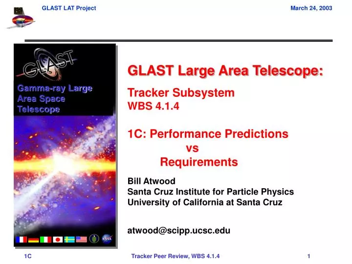
Gamma-ray Large Area Space Telescope. GLAST Large Area Telescope: Tracker Subsystem WBS 4.1.4 1C: Performance Predictions vs Requirements Bill Atwood Santa Cruz Institute for Particle Physics University of California at Santa Cruz atwood@scipp.ucsc.edu.

E N D
Gamma-ray Large Area Space Telescope GLAST Large Area Telescope: Tracker Subsystem WBS 4.1.4 1C: Performance Predictions vs Requirements Bill Atwood Santa Cruz Institute for Particle Physics University of California at Santa Cruz atwood@scipp.ucsc.edu
Level III Performance Specification • Level III Performance for the Tracker Subsystem • LAT-SS-0017-1 LAT TKR Subsystem Specification - Level III Specification • Applicable LAT documents to this review: • LAT-TD-00178 Tracker Reliability Analysis • LAT-SS-00177 LAT TKR Tracker Dimensions and Masses • LAT-TD-01128 Mini TKR Trigger Timing Study • LAT-TD-00201 End-of-Mission Noise in GLAST Silicon Detectors • LAT-TD-00086 Results from Testing of the LAT SSD Prototypes • LAT-TD-00128 Heavy Ion Irradiation of LAT Silicon Strip Detectors • LAT-TD-01078 SSD QA: Irradiations up to October 2002 • LAT-TD-01060 Trigger Noise Rate Measurements on a Tracker Ladder • LAT-TD-01090 Test results on the Tracker ASIC prototypes
Tracker Subsystem Requirements Flow Down Level I Project Specifications FIGURE 2-1 SPECIFICATION TREE Program Plan Requirements Level II System Specifications Level II(a) System Operations Concept Document GLAST00089 Science Req’ts Document GLAST00010 Mission Assurance Requirements GLAST00110 Mission System Specification GLAST00074 Level II(b) Element Spacecraft Performance Spec. LV Interface Specification SC-SI Interface Specification GLAST00038 GBM Instrument Performance Spec. LAT Instrument Performance Spec. LAT-SS-00010 SGL Comm Interface Spec. Inter-Center Interface Spec. GBM IOC Specification Science Support Center Spec. Mission Operations Center Spec. LAT IOC Performance Spec. LAT-SS-00015 Level III Subsystem Specifications LAT - ACD Spec. LAT-SS-00016 LAT - TKR Spec. LAT-SS-00017 LAT - CAL Spec. LAT-SS-00018 LAT SAS Spec. LAT-SS-00020 T&DF Spec. LAT-SS-00019 Aux. Subsystem Spec. LAT-SS-000xx LAT IOC Spec. LAT-SS-00021 LAT Interface Spec. LAT-SS-000xx
Verifications 5.2 Gamma Ray Conversion Efficiency Requirement: The TKR shall convert at least 65% of the gamma rays with energy >10 GeV impinging upon the device at normal incidence. Science impact: effective area Design impact: amount of W converter Verification Method: Analysis Prob(conv) = 1-e-7/9x0 where x0 is the radiation lengths in the Tracker x0 = 12 0.03 + 4 0.18 + 18 0.015 = 1.35 Hence Prob.(conv) = 65.01% MC cross check: #Triggers = 34000 per 100K over 6 m2. Geo Area of Tracker = 2.205 m2 No. that hit Geo. Area of Tracker = 36750 Percent triggering: 23223/36750 = 63.2% Differences: Wall material, tray closeouts, MCM boards, MC run at 0o-5o off normal
Verifications 5.3 Converter Configuration Requirement: At least 25% of the gamma-ray conversions shall occur in high-Z converter foils no greater than 3.5% radiation lengths thick, with the remainder occurring in other material and converter material no more than 25% radiation lengths thick. Method: Analysis Total Thin Converters = 120.03 = .36 rl. Total everything else = 40.18 + 180.015 = 0.99 rl. Hence: 0.36/1.35 = 26.7% The implicit assumption in this approach is that the beam intensity does not vary with depth. So Alternatively: Prob. of Conversion in Thin = 1-e-7/9x0 where x0 = 120.03 = 0.36. Hence Prob. (Thin) = 24.4% Thus percentage of gamma’s converting in the thin of all gamma conversions is Prob. –Thin relative to all Conversions = .244/.6501 = 37.56%
Verifications 5.3.1 Converter/Sensor Spacing Requirement: The converter material shall not lie more than 3 mm above the corresponding sensors. Method: Analysis Bond Thickness: .1 mm Bias Plane Thickness: .1 mm Bias Plane-SSD Bond: .15mm SSD’s: .4 mm Gap Between Planes: 2.13 mm. Hence from converter exit side to top side of furthest SSD = 2.88 mm
Verifications 5.4.1 Within a module active volume Requirement: At normal incidence and within the active area of the thin-converter region, no more than 35% of the gamma-ray conversions shall occur in material other than the high-Z converter foils. Method: Analysis Converters: .03 rl. Other materials (SSD + Tray): .0145rl. Total: .0445 rl. Percentage in Converter = .03/.0445 = 67.4% . Hence 32.6% of conversion do not occur in converters
Verifications 5.4.2 Material Between Modules Requirement: A particle traversing the boundary between TKR modules and at normal incidence to the module wall shall not encounter more than 5% radiation lengths of material, on average. Method: Analysis The items crossed are Tower Wall (1.5mm): .0098 r.l. Tray Closeout (5 mm): .0137 r.l. MCM (1.1 mm): .0093 r.l.) Closeouts cover 91% of total wall area MCM cover 71% of every other wall Traversal between towers doubles Wall & Closeout numbers Average material = 2 x Wall + 2 x .9xCloseout + .7xMCM = .0511 (Requirement was .05)
Verifications 5.5 Geometric Area Requirement: The TKR shall have an active area at normal incidence of at least 19,000 cm2. Method: Analysis The active area of an SSD: ASSD = (89.5-2*.974)mm x (89.5-2*.964)mm = 87.55mm x 87.57mm ASSD = 7666.9 mm2 = 7.667 x 10⁻³ m2 No. of SSD’s in a layer : 16 per tower x 16 towers = 256 AACTIVE = 256 * ASSD = 1.963 m2 = 19,630 cm2
Verifications 5.6 Aspect Ratio Requirement: The ratio of height to width of the TKR active volume shall not exceed 0.45 (for large field-of-view). Method: Analysis Module Height: 624.7 mm Module Width: 1486.5 mm (4 Module width) Aspect Ratio: 624.7 mm / 1486.5 mm = .4202
Verifications 5.7 Charged Particle Detection Requirement: The TKR shall measure immediately following each converter foil, in both x and y views and within the active area, the position of passage of a minimum ionizing particle at normal incidence with an efficiency of greater than 98%. Method: Test & Analysis SSD Eff. measured to be > 99% Eff. At normal incidence the average signal to the SSD comparitor is > .5*32000 e- equiv. To be compared with a noise of < 2000 e- equiv. For a threshold of 8000 e- equiv ( 4+s above the noise) or 1/4 MIP, would require a fluctuation of 20s (16000-8000 / sqrt(16000) = 8000/400) to not be counted. The plot at the right shows the Hit Efficiency for the BTEM using both cosmic rays as well as the well as the electron beam at SLAC. The Electron beam measurements are the more reliable as the direction, energy and nature of the incoming is controlled.
Verifications 5.8 Spatial Measurement Resolution Requirement: The TKR shall measure the direction of a charged particle of straight trajectory (negligible multiple scattering), in both x and y views and using just two consecutive measurement planes, to a precision of no worse than 0.2. Method: Analysis SSD Pitch = .228 mm with a > 32.1 distance between measuring planes. Hence the projected angle error is: 2.9 mrad = .17o This accuracy persists even as the trajectory departs for normal incidence Due to the finite thickness of the SSDs. Note however that the space angle error is ~ 1.5 times larger or .25o
Verifications 5.9 Dead Area Requirement: The fraction of non-active area presented by the top of the TKR shall not exceed 12%. Method: Analysis From 5.5: AACTIVE = 1.963 m2 AGEOM = (Tower Pitch x 4 – 1 Tower Gap)2 = (372*4 – 1.5) = 2.210 m2 Percentage Dead Area: ADEAD = 1 – AACTIVE/AGEOM = 11.2%
Verifications 5.10 Ionization Measurement Requirement: For an event with a single track detected, the TKR shall distinguish, on the basis of charge deposition, a single minimum-ionizing particle from two minimum-ionizing particles to a level of at least 1-sigma. Method: Analysis and Test The right-hand plot shows the Monte Carlo expectation for 1 GeV photon conversions. The first peak is caused by single charged particles crossing a strip while the second peak results when both the e+ and e- from the conversion cross a single strip. The expectation for a single particle is a TOT of 6.5 msec with and rms of 2.3 msec. The GLAST detectors and front end electronics have been adapted for use in low energy proton beams for use in medical studies and an extensive set of measurements and test were done to measure both the linearity, resolution, and absolute calibration of the TOT system. Shown in the figure on the left are TOT distributions for various energy protons which can then be used to estimate the ionization depositions. Excellent agreement with the predicted values was found and a single MIP was measure to have a mean TOT of 7.0 msec with an rms of 1.7 msec. This places the 1 vs 2 MIP distributions more then > 4s apart.
Verifications 5.11 Self Trigger Requirement: The TKR shall provide prompt signals to be used by the T&DF system to form a trigger for readout of the TKR and other sub-detectors. Method: Demonstration The layered OR’s form each plane is made into a 6 fold coincidence with nearest 5 Planes (X or Y. Note that planes come in X-Y pairs) – or more simply put the 3-In-A-Row trigger demands 3 XY pairs of adjacent hits. This trigger was tested and used in the 1999 Beam test and the subsequent Balloon flight successfully.
Verifications 5.11.1 Trigger Efficiency Requirement: The TKR trigger shall be on average at least 90% efficient for the set of gamma-ray conversions from which the conversion products traverse the active areas of at least 3 consecutive measurement planes. Method: Analysis and Test Tests validate the assumption that the individual SSDs are > 99% Eff. Thus the major component of Trigger inefficiency comes from the various dead areas. WHAT % OF EVENTS HAVE JUST 3 LAYERS? From MC at 100 MeV percentage of found tracks with 6 hits = 2182/17075 = 12.8%. This is an over estimate for “just 3 layer events” as a portion of these are events with more hits, but only 6 are picked up and used in the reconstruction. OF THOSE WHAT PERCENT TRIGGER? Chance of getting all 3 layers: .893 = 70% thus we miss 30% of these 3-layer events. Overall we miss < .30 * .128 = 3.84% of all events due to dead areas in the tracker.
Verifications 5.11.2 Trigger Noise Requirement: In the case that no charged particles or gamma rays are incident upon the TKR, the TKR trigger shall not exceed a rate of 500Hz. Method: Test and Analysis Until a full tower is available, estimating the trigger noise from single SSD noise rates is the best that is available. A component of the false trigger rate is driven by the stochastic noise rate (see 5.12 below). This is a calculable probability whose solution is: The measure occupancy rate for the LAT SSD is below 10-5 which should yield a trigger rate well below 500 Hz (estimate ~ few Hz for the full LAT instrument.)
Verifications 5.11.3 Trigger Saturation Recovery Time Requirement: The trigger signals from a TKR readout module shall not hold true for longer than 250 s in the case of passage of a high-momentum fully-ionized iron nucleus. Method: Analysis and Test The output from the comparitor was observed directly (via test pad, probe, and scope) with varying amounts of charged injected into the front end amplifier. The signal reached a maximum length of150 msec for 550 fC of charge at which point it saturated and did not increase out to the maximum tested (4000 fC). The passage of a fully ionized Fe nucleus would deposit 3448 fC.
Verifications 5.12 Data Noise Occupancy Requirement: The noise occupancy in the TKR data stream shall not exceed one in 10,000 channels per trigger. Method: Test The layer-OR rate was measured as a function of the threshold as shown at the right. The envisione trigger thresshold is ~ 1.3 fC (or ¼ MIP). At that point in the plot the per channel rate is < 1 Hz per. For a gate of 1 msec this will yield a chance coincidence of ~ 10-6 well below the 10-4. This measurement has been done several times on different sets of chips; all have given similar results
Verifications 5.13 Dead Time Requirement: The dead time imposed by the TKR readout shall not exceed 10% at a cosmic-ray trigger rate of 10 kHz. Method: Test and Analysis From the initiation of a Layer-OR trigger signal, it takes < 2 msec for a trigger to be returned to the tracker front end to latch in the high (hit) channels. For each channel there is a four deep buffer allowing for successive triggers to occur without causing additional dead time associated with latching data into the front end chips. In the worse case where a cosmic ray causes 2 front end chips to fire in a layer with only one functional read-controller chip, a total of 200 clock cycles @ 20 MHz (10 msec) is required to transfer the data to the read-controller chip. Lastly the transfer of data down the tower from the read-controllers (9 read-controllers per transfer line), again for this worse case 531 clock cycles (26.6 msec) are required. This is the ultimate limit – namely when the sustained trigger rate approaches 37.6 kHz, the read controller chip buffers are full and there is 100% dead time. Because of the highly buffered nature of the system, appreciable dead time will mount very slowly prior to this point (e.g. at 10 kHz the dead time due to latching will be ~2%). We also note however that the tracker does not set the trigger dead time. The calorimeter holds off new triggers for ~ 20 msec, required to digitize the data and this system has no buffering (i.e. ~ 20% dead time at 10 kHz)
Verifications 5.14 Tracker Mass Requirement: The mass of the TKR shall not exceed 530 kg. Method: Test Since no complete towers have yet been constructed it presently is not possible to measure the total mass. However the masses of all of the pieces is now well known and measured. The results of a complete mass audit for the tracker now stands at 517.27 kg (including the redesigned bottom tray and flexture mounts)
Verifications 5.15 Tracker Power Requirement: The power consumption of the TKR shall not exceed 184 W of conditioned power. Method: Test The power required to run completed MCM have been measured to be 250 mW using the G chip and 239 mW using the F chip. These are for running with a 20 MHz clock. Hence the total tracker power is anticipated to be 144 W (138 W) for the G (F) chip version.
Verifications 5.16 Control Signals Requirement: The TKR shall receive control signals from the T&DF system to reset and to configure its readout, to perform in-flight calibration tasks, to trigger acquisition of events, and to control the flow of data to the T&DF. Method: Demonstration The various proto-type units have been operated in this manner.
Verifications 5.16.1 Configuration Read-Back Requirement: The TKR shall provide a facility for read-back of all electronic configuration settings. Method: Demonstration The various proto-type units have been shown to have this functionality
Verifications 5.17 Data Flow Requirement:The TKR shall deliver its data in a zero-suppressed format to the T&DF system, by way of at least two independent paths. Method: Demonstration The various proto-type units have been operated in this manner.
Verifications 5.18 Internal Calibration System Requirement:The TKR readout electronics shall include a system for calibration and test by means of injection of signals and trigger from the T&DF system. Method: Demonstration The various proto-type units have been shown to have this functionality. The system is comprised of a DAC onboard each of the front end chips (64 channels) which is programmable. This DAC controls the amount of charge injected into the pre-amps during test. This has been one of the ways used to measure the noise and gain of individual channels.
Verifications 5.19 Temperature Monitoring Requirement:The TKR shall provide temperature sensors within its volume for monitoring the TKR temperature and temperature gradient. Method: Demonstration On each tower there will be a total of 16 thermistors (2 per controller-readout cable – 8 cables per tower). These sensors are spread out along the tower’s length and various sides to provide for the monitoring of the temperatures at there locations.
Verifications 5.20 Thermal Control Requirement: The TKR shall be cooled by passive flow of heat through its interface to the Grid. Method: Test and Analysis As no completed towers have yet been made a full test has yet to be done. However a complete thermal model of the tower has been made and shows that with the chosen side wall material and connection to the LAT Grid, a thermal gradient of less then 10 oC from the Grid to the top of a tower is expected.
Verifications 5.21 Environmental Requirement: The TKR shall meet the structural and thermal environment requirements defined in its interface control document. Method: Test As no completed towers have yet been made a full test has yet to be done. However, to date, we expect the design to meet or exceed all of the ICD requirements
Verifications 5.22 Reliability Requirement: The reliability of the tracker shall be at least 96% in five years. Reliability is the probability that the tracker will not experience a reduction in operability below 90% due to failure of its components. Operability is the percentage of tracker channels that are operational. Method: Analysis This has been analyized by assessing what possible failure modes exist (16 were indentified). For each its impact on the mission (ranked 1 – 5 from most to least sever) and its probability of occurrence (again ranked 1- 5 where 1 is > 10% , 3 < 1%, and 4 and 5 are considered very unlikely). Of the 16, 2 were judged to have a severity level of 2 and one had a level of 3. The rest were either at level 4 or 5 with essentially little impact on the mission. The 2 at severity level 2 involve the loss of a non-redundant TEM part or the lost of a redundant TEM part. This would cause the loss of a tower (1/16 of the detector). The probability of this to occur for the identified parts was deemed to be to small to allow for a credible estimate. In the case of a redundant part failure of course the impact is nil. The one item flagged at severity level 3 was an MCM failure either through corruption of the data transmission electronics or through the bias voltage distribution. This could cause the loss of one side of a tray ( 1 out of 36 per tower). After burn-in of these electronic modules the probability of failure in less then 5 years was deemed to small to allow for a reliable estimate.