Download
1 / 36
370 likes | 395 Views
ZigBee Primer. IEEE 802.15.4 radio Line-powered routers, low power edge nodes Just like WiFi… …Why not use WiFi? Single frequency – why? Edge nodes can wake up and TX whenever they want. Routers must be ready. Claim: Single-frequency narrow-band communication is unreliable.

E N D
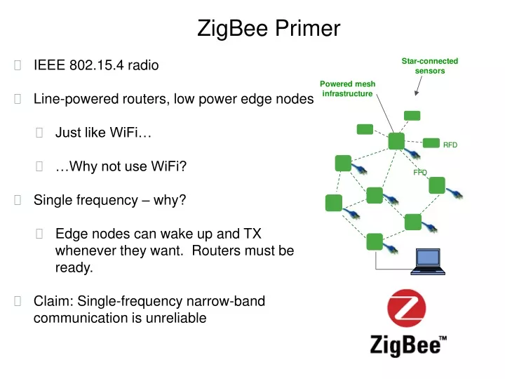
ZigBee Primer • IEEE 802.15.4 radio • Line-powered routers, low power edge nodes • Just like WiFi… • …Why not use WiFi? • Single frequency – why? • Edge nodes can wake up and TX whenever they want. Routers must be ready. • Claim: Single-frequency narrow-band communication is unreliable
Consider one path E ~ 1/R; P ~ 1/R2 metal Now received energy depends on both distances. At some distances, the two waves will interfere constructively, and at others they interfere destructively. These nulls depend on wavelength and the relative distances
R-2 -30dBm -60dBm The reflective surface is 10,000m away -90dBm 100m 1km 1m 10m
R-2 -30dBm -60dBm The reflecting surface is 100m away -90dBm 100m 1km 1m 10m
-30dBm The reflecting surface is 10m away -90dBm 100m 1km 1m 10m
R-2 -30dBm -60dBm The reflecting surface is 1m away R-4 -90dBm 100m 1km 1m 10m
-50dBm -70dBm The reflecting surface is 2m away from one node and 8m from the other -90dBm 100m 1km 1m 10m
-50dBm Add a second reflecting surface 10m away from both antennas (like a metal ceiling) and it changes again -90dBm 100m 1km 1m 10m
Multipath Fading ch.11
Multipath Fading 0% reliability 100% reliability ch.11 ch.12
Multipath Fading ch.11 ch.12 ch.19 ch.20 ch.13 ch.14 ch.21 ch.22 ch.15 ch.16 ch.23 ch.24 ch.17 ch.18 ch.25 ch.26
Average RX power vs. Distance -40 -50 -60 -70 PR [dBm] -80 -90 -100 0 20 40 60 Distance [meters]
Path Stability by 802.15.4 Channel 2.480 GHz 802.11bg Channels 802.15.4 Channels 2.405 GHz Each dot is the 15 minute average
Power-optimal communication A B A wakes up and listens B transmits B receives ACK A transmits ACK Worst case A/B clock skew • Assume all motes share a network-wide synchronized sense of time, accurate to ~1ms • For an optimally efficient network, mote A will only be awake when mote B needs to talk Expected packet start time
Packet transmission and acknowledgement Radio TX startup ACK RX Packet TX Radio TX/RX turnaround Mote Current (2011): 15 mC (2008): 50 mC Charge cost (2003): 300 mC
Timing – imperfect synchronization (latest possible transmitter) CCA: RX startup, listen, RX->TX A Transmit Packet: Preamble, SS, Headers, Payload,MIC, CRC RX startup or Tx->Rx Tg ACK RX ACK Tcrypto B RX startup Tg Tg RX packet Verify CRC Verify MAC MIC Calculate ACK MIC+CRC Transmit ACK RX->TX Expected first bit of preamble • TCCA = 0.512ms to be standards compliant • Worst case is a receive slot followed by a transmit slot to a different partner, as radio will be finishing up the ACK TX just as it needs to look for a clear channel, so • TCCA = TTX->RX + Tchannel assessment + TRX->TX = 0.192ms + 0.128ms + 0.192ms • Tpacket = 4.256ms for a maximum length packet • Preamble+SS+packet = 4+1+128B = 133B = 1064 bits 4.256ms @ 250kbps • Tcrypto is the total time to verify packet MIC and create ACK MIC • TgACK is the tolerance to variation in Tcrypto and/or mote B’s turnaround time from RX to TX • TACK is a function of the ACK length. It is likely to be just under 1ms. • Tslot = TCCA+2*Tg+Tpacket+Tcrypto+TgACK+TACK = 0.512+2+4.256+1+0.1+1 = 9ms
Fundamental platform-specific energy requirements • Packet energy & packet rate determine power • (QTX + QRX )/ Tcycle • E.g. (60 uC + 40 uC) /10s = 10 uA
Scheduled Communication Slots A B B TX, A ACK Ch 3 Ch 4 Ch 5 Ch 7 Ch 8 Ch 6 • Mote A can listen more often than mote B transmits • Since both are time synchronized, a different radio frequency can be used at each wakeup • Time sync information transmitted in both directions with every packet
Idle listen (no packet exchanged) Empty receive Radio RX startup Mote Current (2011): 5 mC (2008): 27 mC Charge cost (2003): 70 mC
Latency reduction • Energy cost of latency reduction is easy to calculate: • Qlisten / Tlisten • E.g. 20uC/1s = 20uA • Low-cost “virtual on” capability • Latency vs. power tradeoff can vary by mote, time of day, recent traffic, etc.
Multi-hop routing A B G • Global time synchronization allows sequential ordering of links in a “superframe” • Measured average latency over many hops is Tframe/2 T2, ch y T1, ch x Superframe
TSMP Foundations • Time Synchronization • Reliability • Power • Sensor • Reliability • Frequency diversity • Multi-path fading, interference • Spatial diversity • True mesh (multiple paths at each hop) • Temporal diversity • Secure link-layer ACK • Power • Turning radios off is easy
Link 53 37 A link defines a timeslot and channel offset.
Graph 17 47 53 41 37 43 A graph is a collection of connections and the links belonging to them A graph contains both routing and capacity Similarities to ATM circuits, flow labels, and Cisco tag switching (MPLS)
Superframe – repeating TDMA schedule • Color indicates TX slot for mote of that color • Wake up: RX? TX? • Use time+channel offset to calculate RF frequency (pseudo-random) • Similar to GSM, but with channel hopping One Slot Time Channel offset
High throughput – multiple hops • Use multiple channels • Only need 2 time slots • Throughput is 50 packets/second • independent of n • Limited by worst PDR (not combination) Odd slots Even slots Odd slots Even slots Odd slots
Link = (Time Slot, Channel Offset) D B • All of B’s transmit links are dedicated and won’t collide • B has twice as much bandwidth to A as to C • B can broadcast to E and F, or use that link of a unicast to one or the other • D and C share a link for transmitting to A. A backoff algorithm is needed in case of collisions. One Slot Time Chan. offset A BA CA DA C BA BC E F BE BF
Time Synchronization Timestamps available to application RMS <0.1ms with Wireless HART RMS <0.01ms with SmartMesh IP
Standards • Industrial Standards based on TSMP • Wireless HART, 2007 (IEC62591, 2010) • ISA100.11A, 2009, 2010 • WIA-PA • IPSO Alliance, 2008 – IP for Smart Objects • Created to bring IPv6 to Zigbee SE 2.0 • IEEE 802.15.4E, 2012 • TSCH - time synchronized channel hopping • Rolled into 802.15.4-2015, 2015 • IETF • 6LoWPAN, CoAP • RFC 6550, 2012 • RPL – routing protocol for low-power lossey networks • 6TiSCH, 2013 • Minimal – simplest IPv6 on TSCH configuration • 6top – peer-to-peer link negotiation • security
Various 15.4 stacks Zigbee Smart Energy 1.0, 2.0 ISA100 CoAP Wi-SUN UDP/TCP Zigbee 2004 Zigbee 2006 Zigbee Pro 2007 RPL (central) UDP Wireless HART 6LoWPAN 6LoWPAN 6TiSCH ? (central) 802.15.4E Stupid-MAC – single channel, powered routers 802.15.4 802.15.4G
Multi-platform, multi-OS interoperability (2012)openWSN.berkeley.edu http xyz CoAP UDP TCP 6LoWPAN, RPL PLC WiFi 802.15.4E - TSCH PLC WiFi 2.4 GHz 802.15.4 • Dust Networks • Huron (Dust Oski) • uC/OS-II • OpenWSN • SmartMeshIP • UCB, • GINA (MSP,Atmel‘231) • OpenOS • OpenWSN LBNL Jennic JN5148FreeRTOS
Scavenging Wireless HART Products • Battery • Vibration • Battery • 4-20 mA loop • Solar • Battery • 4-20 mA loop • Thermal