Download
1 / 7
70 likes | 279 Views
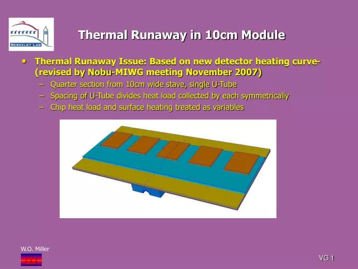
Thermal Runaway in 10cm Module. Thermal Runaway Issue: Based on new detector heating curve- (revised by Nobu-MIWG meeting November 2007) Quarter section from 10cm wide stave, single U-Tube Spacing of U-Tube divides heat load collected by each symmetrically

E N D
Thermal Runaway in 10cm Module • Thermal Runaway Issue: Based on new detector heating curve- (revised by Nobu-MIWG meeting November 2007) • Quarter section from 10cm wide stave, single U-Tube • Spacing of U-Tube divides heat load collected by each symmetrically • Chip heat load and surface heating treated as variables VG 1
Surface Heating Curve New curve based on 1mW/mm2 at 0ºC (Nobu-MIWG No. 2007) and exponential temperature dependence VG 3
Thermal Runaway Solutions Plot of peak detector temperature leading up to runaway (as function of tube surface wall temperature) Surface heating 1mW/mm2 @ 0C Exponential temperature dependency (Nobu-MIWG Mtg. Nov. 2007) VG 4
Thermal Runaway-Variable Surface Heating Comparing effect of surface heating using 0.25W/chip as baseline SurfaceHeating 1mW/mm2 0 2mW/mm2 VG 5
Detector Surface Heating Curve at right shows slight deviation of solution convergence Deviation caused by using peak silicon nodal temperature whereas solution is based on the detector outer surface edge average VG 6
Thermal Runaway-Typical Thermal Plot Chip: 0.5W Coolant Tube Surface -16.8ºC Peak chip: 6.18ºC Peak detector edge: 5.17ºC Throughout solutions peak chip and peak detector differential temperature stays near 1.0 to 1.1ºC With 0.25W/chip the temp difference is nominally 0.5ºC Nearly thermal runaway point VG 7