Download
1 / 37
370 likes | 378 Views
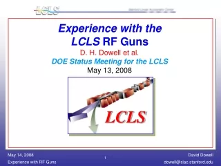
LCLS Commissioning: Results & Plans P. Emma, for the LCLS Commissioning Team DOE Status Meeting for the LCLS May 13, 2008. LCLS. Phys. Rev. publication: http://prst-ab.aps.org/pdf/PRSTAB/v11/i3/e030703. beam parked here. Injector Commissioned (‘07). Commissioned in Jan. 2008.

E N D
LCLS Commissioning:Results & PlansP. Emma,for theLCLS Commissioning TeamDOE Status Meeting for the LCLSMay 13, 2008 LCLS Phys. Rev. publication: http://prst-ab.aps.org/pdf/PRSTAB/v11/i3/e030703
beam parked here Injector Commissioned (‘07) Commissioned in Jan. 2008 LCLS Accelerator Layout 250 MeV z 0.19 mm 1.6 % 4.30 GeV z 0.022 mm 0.71 % 13.6 GeV z 0.022 mm 0.01 % 6 MeV z 0.83 mm 0.05 % 135 MeV z 0.83 mm 0.10 % Linac-X L =0.6 m rf= -160 Linac-0 L =6 m rf gun L0-a,b Linac-3 L 550 m rf 0° Linac-1 L 9 m rf -25° Linac-2 L 330 m rf -41° 25-1a 30-8c 21-3b 24-6d ...existing linac 21-1 b,c,d undulator L =130 m X BC1 L 6 m R56 -39 mm BC2 L 22 m R56 -25 mm DL1 L 12 m R56 0 DL2 L =275 m R56 0 SLAC linac tunnel research yard
LCLS Injector Layout 6 MeV OTR screens (7) YAG screens (7) Wire scanners (7) RF Gun Dipole magnets (8) Commissioned in ‘07 Solenoid Beam stoppers (2) S-band RF acc. sections (5) L0a Gun Spectrometer L0b Emittance Screens/Wires Emittance Screen/Wires RF Deflector L1S 2-km point in 3-km SLAC linac X-band RF acc. section BC1 135-MeV Spectrometer TD11 stopper 135 MeV 250 MeV
New installation in fall ‘07 LCLS BC2 Area Layout (sector 24/25) OTR screens (3) Collimator jaws (2 Phase monitor cavity (1) Dipole magnets (4) Kicker magnet (1) Transverse RF deflector (1) S-band RF acc. sections 4 wire-scanners “de-scoped” 4 wire-scanners in sec-28 (300 m downstream) CE21 BPMS21 OTR21 PH03 BXKIK TCAV3 (25-2d) OTR22 (25-3d) OTR_TCAV (25-9) BC2 4.3 GeV (not to scale)
Commissioning Highlights • Injector commissioning: April through August, 2007 (DONE) • Phase-II commissioning: Dec. Complete 3/31/08 (BC2 + Linac) • Up to 1 nC of bunch charge now available (0.25 nC used) • Great laser uptime (99%) and good performance (again) • Emittances 1 mmafter BC1 at 1 nC, 250 MeV (fairly routine) • Routine e- to 14 GeV (24/7 except Wed., ~90% up-time) • BC1 dipoles & chicane motion fixed! • No emittance growth in X-band RF cavity when best steered • BC2 compression demonstrated (no dipole field quality issues) • Long transverse RF deflector at 5 GeV fully operational • CSR effects measured in BC1 & BC2 – agree with codes so far • Many beam & RF feedback systems running well • Coherent OTR observed – compromises nearly all screen data • Gun RF probes changed in April ’08 (allows 120-Hz – D. Dowell) • More physicists involved in commissioning in 2008 (8 15)
“Problems/Issues” from July ‘07 DOE Review • Gun Faraday cup broken • Gun toroid shorted during installation • Some YAG screens not installed properly • BC1 motion control limited (300 mm 260 mm) • Cathode QE about 5-times lower than design • Some controls tools late (orbit displays, fitting, magnet control & alarms) • MCOR power supply ADC readback noise (fixed) • Laser phase drift and lock trouble until mid-June ALL FIXED
Pre-Beam Check List for BC2/Linac 17 pages, 800 checks - all DONE polarity checks DONE installation orientation controls check component bar codes etc. etc.
6.9 ps 2008 7.2 ps 2R = 1.4 mm 2008 7.2 ps 99% Drive Laser up time! S. Gilevich, G. Hays, P. Hering, A. Miahnahri, W. White Laser Spatial and Temporal Shaping 2007 2007 Temporal shape (6.9 ps FWHM) Spatial shape on cathode using iris
Watch profiles as scan proceeds Powerful Scanning/Correlation Application H. Loos Quickly minimize emittance by scanning any parameter
before xx = 1.08 sets quads reads meas’d b & a after xx = 1.00 b-Matching GUI in Matlab C. Limborg Soon to be extended for undulator matching…
Projected Emittance <1.2 μm at 1 nC (135 MeV) s = 60 μm gex = 1.07 μm meets injector goals gey = 1.11 μm
Injector Emittance Measured Over 3 Days (0.25 nC) gex = 0.91,gey = 1.01 OTR screen at 135 MeV gex injector is stable gey gex = 0.83,gey = 0.83 wire-scanner at 250 MeV after BC1 J. Welch
Laser & Electron-Based Feedback Systems • Transverse Loops: • Laser spot on cathode (2) • Gun launch angle • Injector trajectory • X-band cavity position • Linac trajectory (2 old) • Undulator traj. (future) • Longitudinal Loops: • DL1 energy • BC1 energy • BC1 bunch length • BC2 energy • BC2 bunch length • Final energy (old loop) now running Laser (bunch length feedback still needs work) BPMs CSR detectors Steering Loop sz1 sz2 V0 d0 gun d3 d1 d2 L0 1 2 V1 V2 V3 D. Fairley J. Wu J. Frisch L2 L3 X L1 DL2 DL1 BC1 BC2
Nov. ‘07 Sext. tolerance Aug. ‘07 ±3s beam BC1 Dipole Field Quality Fixed Poles were milled off and wider poles were bolted on and then the fields were shimmed. fixed J. Welch, S. DeBarger, N. Li, et al.
Dex/e0 < 1% hx = -0.64 mm hx = -0.18 mrad No more BC1 emittance growth hy = 1.62 mm Dey/e0 3% hy = -1.33 mrad Dex/e0 (1st-order) < 1% gex = 0.88 mm Dex/e0 (2nd-order) < 5% BC1 Dispersion Measurement & Correction Vary energy before BC1 and read BPMs after BC1 h, h
No measurable quad field and sextupole is just attolerance BC2 Dipole Field Quality OK Beam energy scans confirm BC2 dipole field quality meets requirements ±3s beam OK
Operating Point Summary Display Shows operators the main machine parameter targets and their present settings & includes save/restore files H.-D. Nuhn
BPM L1S Bunch length after BC1 measured with transverse RF BC1 (250 MeV) BC2 OFF BSY (14 GeV) TCAV (5.0 GeV) A Phase shift of -0.4 deg is added to the Elegant curves CSR energy loss after BC1 measured with BPM Elegant e- operating point g BPM-Measured CSR Energy Loss in BC1 at 0.25 nC (compares well with tracking) Y. Ding, Z. Huang Chicane Bend BPM
sx = 38 mm sx = 55 mm sx = 246 mm j = -22º j = -26º j = -27º Verticalemittance after BC1 is almost unaffected Y. Ding, Z. Huang Elegant Hor. CSR Emittance Growth after BC1 (250 MeV, 0.25 nC) Horizontalemittance after BC1 vs. RF phase Elegant Meas-1 Meas-2 Data also exists at 1 nC and BC2 data (0.25 nC) also shows decent results Elegant operating point
RF Phase and Amplitude Stability (e.g., L0a) New inj. RF systems meet jitter tolerances 0.05% rms (<0.07%) RF Feedback Running 20-second sample at 10 Hz 0.05º rms (<0.07º) R. Akre, D. Kotturi, J. Craft, V. Pacak, et al.
… near end of linac (~15% of rms beam size, but sometimes larger) RMS AxN = 19.9% RMS AyN = 8.5% Thanks to Controls group for new BPM electronics! poor BPM resolution Q = 0.25 nC Normalized phase space centroid jitter after BC1 (~5% of rms beam size) RMS AyN = 4.1% RMS AxN = 4.9% Stability is not so far off of our goals (~10%) 1-s beam size D. Ratner DE/E jitter < 0.1% DQ/Q jitter < 2%
BC2 Chicane in the Linac at 4.3 GeV Bob Fuller Chicane length 24 m, 4.3 GeV, 2º bends
sz < 10 mm Bunch length after BC2 measured with transverse RF old screen used – poor res. sz 10 mm -2º shift applied to simulation BC2 (4.3 GeV) TCAV (5.0 GeV) BSY (14 GeV) 550 m Bunch Compression Measured after BC2 (0.25 nC) sz > 25 mm L2
Longitudinal Phase Space at 14 GeV PR55 LiTrack simulation Bunch is Over-Compressed L2 phase = -41 deg Chirp knob = -450 MeV Vertical scale only approx. measurement PR55 Bunch is Under-Compressed L2 phase = -41 deg Chirp knob = +450 MeV LiTrack simulation Vertical scale only approx. measurement older screen has poor resolution
sx = 76 mm sx = 38 mm sx = 49 mm sx = 47 mm wire scans Emittance Measurements at End of Linac Using Wire Scanners F.-J. Decker R. Iverson Emittance measured 300 m after BC2 at 10 GeV with 10 mm bunch length gey = 0.9 mm Q = 0.25 nC Results still variable – requires careful work
Poor Beam Conditions Also Arise… bad X-profile at end of linac Possibly the L2 phase drifted into a strong CSR regime – bunch length feedback not running gex = 5.5 mm Q = 0.25 nC
gey stayed at ~1 mm for the next 3+ days Emittance Near End of Linac Over a Weekend gex gey Emittance near end of linac during weekend run at 0.25 nC, with no tuning
2008 Commissioning Goals DONE http://www-ssrl.slac.stanford.edu/lcls/internals/commissioning/documents/bc2-commissioninggoals.doc DONE DONE DONE DONE DONE
LTU/Und Comm. Linac/BC2 Commissioning Re-commission Inj/BC2 to SL2 NEH Operations/ Commissioning FEE Comm. LCLS Installation and Commissioning Time-Line First Light in FEE First Light in FEH Und. Seg. Install PPS Cert. LTU/Dump LTU/Und/Dump Install X-Rays in NEH CD-4 (7/31/2010) FEE/NEH Install FEH Hutch BO FEH Install PEP-II run ends now J F M A M J J A S O N D J F M A M J J A S O N D J F M A M J J A A M 2008 2009 2010 Down PPS May 2, 2008
LTU/Undulator/FEE/FEL Commissioning H. Tompkins • See break-out presentations: • LTU & Undulator Commissioning Plans (H.-D. Nuhn) • FEL/FEE Overview Commissioning Plans (H. Tompkins) • FEE Diagnostics & Commissioning (R. Bionta)
Problems/Issues • End-of-linac x-emittance difficult to minimize and maintain, especially at 1 nC (needs more work – m-bunching?) • Some wire-scanner vibration issues (~fixed in April ‘08) • Most OTR screens are unusable due to COTR (laser heater should solve this in FY2009) • Most linac BPMs need upgrade – 16 of 83 done with great resolution improvement (on AIP list) • BC2 bunch length monitor noisy or real jitter – (need beam synchronous acquisition for RF & BPMs or m-bunching?) • Bunch length feedback loops need more wring-out (need more time + less noisy monitor)
Summary • Drive laser very reliable – performs well (great team) • Injector in very good shape – runs well after setup • Many measurements made – getting to know machine • Emittances at end of linac difficult to tune and maintain, but nice results are possible with effort (gey is maybe there?) • We look forward to next phase (LTU, undulator, FEL, …) –preparations have begun (plans, software, checkout, …) • Thanks to dedicated Commissioning Team + Controls, RF, Engineering, Operations, ASD, maintenance, etc
m-Bunching in BC2 May Blow up X-Emittance OTR screen in BC2 OTR21 gex,ymeasured with wire-scanners 500-m downbeam of BC2 gex gey
COTR After BC2 OTR screen just after BC2 OTR22 OTR22 with BC2 screen OUT (m-bunching present – COTR!) with BC2 screen inserted (smoothes m-bunching)
FY2009 Commissioning Activities • Pre-Beam Checkout (Nov-Dec ‘08) – check-list in prep. • Re-establish injector & linac beam quality (Nov-Dec ‘08) – have experience • First LTU Commissioning with beam (Jan-Mar ‘09) – lots of time • ‘Undulator’/Dump Comm. without undulators (Jan-Mar ‘09) • Calibrate & commission: RF BPMs, Loss Monitors, BFWs, ADS • BBA algorithm testing (without segments) • Install undulator segments (Mar ’09, two wks) – optimize linac again • First Undulator Segments Commissioning (Mar-Apr ‘09) • Care with first transport to minimize radiation on segments • Full alignment process (BBA, BFW’s) • Commission FEE Diagnostics (Apr-Jun ‘09) • Direct Imager, Calorimeter, Slit, Solid Attenuator, Gas Attenuator, Gas Detector • Beam-Based K Measurement Components • Optimization & characterization of SASE (Jun-Jul ‘09) • Optimize linac beam quality (adjust compression, emittance tuning, BBA) • Measure gain length