Download
1 / 1
10 likes | 117 Views
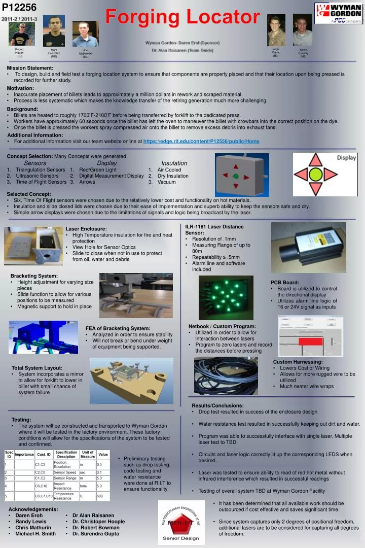
P12256. Forging Locator. 2011-2 / 2011-3. Wyman Gordon- Daren Eroh (Sponsor) Dr. Alan Raisanen (Team Guide). Jorge Viana (IE). Robert Hagen (EE). Mark Gonzalez (ME). Kevin Conway (ME). Joe Majkowski (EE). Mission Statement:

E N D
P12256 Forging Locator 2011-2 / 2011-3 Wyman Gordon- Daren Eroh(Sponsor) Dr. Alan Raisanen (Team Guide) Jorge Viana (IE) Robert Hagen (EE) Mark Gonzalez (ME) Kevin Conway (ME) Joe Majkowski (EE) • Mission Statement: • To design, build and field test a forging location system to ensure that components are properly placed and that their location upon being pressed is recorded for further study. • Motivation: • Inaccurate placement of billets leads to approximately a million dollars in rework and scraped material. • Process is less systematic which makes the knowledge transfer of the retiring generation much more challenging. • Background: • Billets are heated to roughly 1700̊ F-2100̊ F before being transferred by forklift to the dedicated press. • Workers have approximately 60 seconds once the billet has left the oven to maneuver the billet with crowbars into the correct position on the dye. • Once the billet is pressed the workers spray compressed air onto the billet to remove excess debris into exhaust fans. • Additional Information: • For additional information visit our team website online at https://edge.rit.edu/content/P12556/public/Home Concept Selection: Many Concepts were generated Sensors Triangulation Sensors Ultrasonic Sensors Time of Flight Sensors Display Red/Green Light Digital Measurement Display Arrows Insulation Air Cooled Dry Insulation Vacuum • Selected Concept: • Six, Time Of Flight sensors were chosen due to the relatively lower cost and functionality on hot materials. • Insulation and slide closed lids were chosen due to their ease of implementation and superb ability to keep the sensors safe and dry. • Simple arrow displays were chosen due to the limitations of signals and logic being broadcast by the laser. • ILR-1181 Laser Distance Sensor: • Resolution of .1mm • Measuring Range of up to 80m • Repeatability ≤ .5mm • Alarm line and software included • Laser Enclosure: • High Temperature insulation for fire and heat protection • View Hole for Sensor Optics • Slide to close when not in use to protect from oil, water and debris • Bracketing System: • Height adjustment for varying size pieces • Slide function to allow for various positions to be measured • Magnetic support to hold in place • PCB Board: • Board is utilized to control the directional display • Utilizes alarm line logic of 16 or 24V signal as inputs • Netbook / Custom Program: • Utilized in order to allow for interaction between lasers • Program to zero lasers and record the distances before pressing • FEA of Bracketing System: • Analyzed in order to ensure stability • Will not break or bend under weight of equipment being supported. • Custom Harnessing: • Lowers Cost of Wiring • Allows for more rugged wire to be utilized • Much neater wire wraps • Total System Layout: • System incorporates a mirror to allow for forklift to lower in billet with small chance of system failure • Results/Conclusions: • Drop test resulted in success of the enclosure design • Water resistance test resulted in successfully keeping out dirt and water. • Program was able to successfully interface with single laser, Multiple laser test to TBD. • Circuits and laser logic correctly lit up the corresponding LEDS when desired. • Laser was tested to ensure ability to read of red hot metal without infrared interference which resulted in successful readings • Testing of overall system TBD at Wyman Gordon Facility • Testing: • The system will be constructed and transported to Wyman Gordon where it will be tested in the factory environment. These factory conditions will allow for the specifications of the system to be tested and confirmed. • Preliminary testing such as drop testing, code testing and water resistance were done at R.I.T to ensure functionality • It has been determined that all available work should be outsourced if cost effective and saves significant time. • Since system captures only 2 degrees of positional freedom, additional lasers are to be considered for capturing all degrees of freedom. • Acknowledgements: • Daren Eroh • Randy Lewis • Chris Mathurin • Michael H. Smith • Dr Alan Raisanen • Dr. Christoper Hoople • Dr. Robert Bowman • Dr. Surendra Gupta