Download
1 / 65
670 likes | 949 Views
Vacuum II. G. Franchetti CAS - Bilbao. Index. Creating Vacuum (continuation) . Measuring Vacuum. Partial Pressure Measurements. Diffusion Ejector pump. Inlet. Schematic of the pump. Cold surface . operating pressure: 10 -3 – 10 -8 mbar. Laminar flow. Outlet. Boiling oil.

E N D
Vacuum II G. Franchetti CAS - Bilbao G. Franchetti
Index Creating Vacuum (continuation) Measuring Vacuum Partial Pressure Measurements G. Franchetti
Diffusion Ejector pump Inlet Schematic of the pump Cold surface operating pressure: 10-3 – 10-8 mbar Laminar flow Outlet Boiling oil G. Franchetti
Inlet Pump principle: Pi The vacuum gas diffuses into the jet and gets kicked by the oil molecules imprinting a downward momentum Cold surface Po Laminar flow The oil jets produces a skirt which separate the inlet from the outlet Outlet Boiling oil G. Franchetti
Inlet Diffusion Outlet G. Franchetti
Problems Inlet Pi Cold surface Po Back streaming Laminar flow Outlet Back-Migration Boiling oil G. Franchetti
Cures Inlet Pi Baffle (reduces the pumping speed of 0.3) Cold surface Cold Cap Po Laminar flow Outlet Cold surface Boiling oil G. Franchetti
with The pumping speed Sm is proportional to the area of the inlet port 100 mm diameter Sm = ~ 250 l/s for N2 LEYBOLD (LEYBODIFF) G. Franchetti
Capture Vacuum Pumps Getter Pumps (evaporable, non-evaporable) Principle Capture vacuum pumps are based on the process of capture of vacuum molecules by surfaces Sputter ion Pumps Cryo Pumps G. Franchetti
Getter Pumps Gas Surface Solid Bulk G. Franchetti
Definition of NEG Getters are materials capable of chemically adsorbing gas molecules. To do so their surface must be clean. For Non-Evaporable Getters a clean surface is obtained by heating to a temperature high enough to dissolve the native oxide layer into the bulk. T = Ta T = RT T = RT Native oxide layer -> no pumping Heating in vacuum Oxide dissolution -> activation Pumping P. Chiggiato NEGs pump most of the gas except rare gases and methane at room temperature
Sorption Speed and Sorption Capacity C.Benvenuti, CAS 2007 G. Franchetti
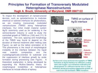
Choice of the coating technique for thin film: sputtering substrate to coat: vacuum chamber target material: NEG (cathode) driving force: electrostatic energy carrier: noble gas ions NEG composition • The trend in vacuum technology consists in moving the pump progressively closer to the vacuum chamber wall. • The ultimate step of this process consists of transforming the vacuum chamber from a gas source into a pump. • One way to do this is by “ex-situ” coating the vacuum chamber with a NEG thin film that will be activated during the “in situ” bakeout of the vacuum system.
Dipole Coating Facility Quadrupole Coating Facility M.C. Bellachioma (GSI) G. Franchetti
Sputter ion pumps Cathode - + Anode E - E P2 B P1 Titanum G. Franchetti
Sputtering process + trapped electrons The adsorbing material is sputtered around the pump G. Franchetti
A glimpse to the complexity ion bombardment with sputtering Adsorbed ions ionization process Trapped electron G. Franchetti
Example of Pumping speed J.M. Laffterty, Vacuum Science, J. Wiley & Son, 1998 G. Franchetti
Cryo Pumps m Stick to the Wall !! v1 Cold Wall Dispersion forces between molecules and surface are stronger then forces between molecules G. Franchetti
Schematic of a cryo pump Vessel nw pw Pw = pressure warm Pc = pressure in the cold Iw = flux Vessel Pump Ic = flux Pump Vessel nc pc Pump cold molecules stick to the cold wall G. Franchetti
By using the state equation Now In the same way If no pumping although Relation between pressures Thermal Transpiration G. Franchetti
When the two pressures breaks the thermal transpiration condition a particle flow starts We find We define and Cryocondensation: Pw is the vapor pressure of the gas at Tc Pc depends on the capture process G. Franchetti
Summary on Pumps N. Marquardt G. Franchetti
Gauges Liquid Manometers MacLeod Gauges Viscosity Gauges Thermal conductivity Gauges Hot Cathode Gauges Alpert-Bayard Gauges Penning Gauges G. Franchetti
Liquid Manometers P2 Relation between the two pressure P1 h issue: measure precisely “h” by eye +/- 0.1 mm but with mercury surface tension depress liquid surface High accuracy is reached by knowing the liquid density Mercury should be handled with care: serious health hazard G. Franchetti
McLeod Gauge First mode of use: The reservoir is raised till the mercury reaches the level of the second branch (which is closed) P2 Closed Δh h0 Quadratic response to P2 Second mode of use: keep the distance Δh constant and measure the distance of the two capillaries linear response in Δh G. Franchetti
Viscosity Gauges ω Gas molecule φ It is based on the principle that gas molecules hitting the sphere surface take away rotational momentum R The angular velocity of the sphere decreases ρ = sphere density α = coefficient of thermal dilatation T = temperature va = thermal velocity G. Franchetti
(K. Jousten, CAS 2007) F.J. Redgrave, S.P. Downes, “Some comments on the stability of Spinning Rotor Gauges”, Vacuum, Vol. 38, 839-842 G. Franchetti
Thermal conductivity Gauges A hot wire is cooled by the energy transport operated by the vacuum gas hot wire Accommodation factor By measuring dE/dt we measure P G. Franchetti
Energy Balance • Energy loss by gas molecules Wc/2 • Energy loss by Radiation WR Wc/2 ε = emissivity • Energy loss by heat conduction V When the energy loss by gas molecule is dominant P can be predicted with contained systematic error G. Franchetti
Pirani Gauge Example of power dissipated by a Pirani Gauge vs Vacuum pressure The Gauge tube is kept at constant temperature and the current is measured So that Through this value E . G. Franchetti
Ionization Gauges Principle electrons + V L accelerating gap G. Franchetti
E new electrons i+ = current proportional to the ionization rate + i- IONIZATION V positive ions G. Franchetti
Electrons ionization rate Sensitivity G. Franchetti
Hot Cathode Gauges Electric field Anode Grid + + 30 V 180V Hot Cathode G. Franchetti
Hot Cathode Gauges In this region the electrons can ionize vacuum particles Anode Grid + + 30 V 180V Hot Cathode A current between grid and anode is proportional to the vacuum pressure i+ i+ G. Franchetti
Limit of use Upper limit: it is roughly the limit of the linear response new electron Lower limit: X-ray limit Anode X-ray The new electron change the ionization current Pm X-ray limit X-ray Grid P G. Franchetti
Alpert-Bayard Gauge The X-ray limit is easily suppressed by a factor ~100-1000 X-ray Hot Cathode Anode X-ray the probability that a new electron hits the anode is now very small Grid G. Franchetti
Schematic of the original design (K. Jousten, CAS 2007) G. Franchetti
Penning Gauge (cold cathode gauges) anode cathode E = electric field B = magnetic field Electrons motion G. Franchetti
Under proper condition of (E,B) electrons get trapped in the Penning Gauge One electron is trapped - - - - - - + + + + + + + + + + + + + + + + - - - - - - - - - - - - - - + G. Franchetti
One electron is trapped - - - - one vacuum neutral gas enters into the trap - - + + + + + + + + + + + + + + + + - - - - - - - - - - - - - - + G. Franchetti
Ionization process Before Collision Collision Ionization Neutral vacuum atom Charged vacuum atom + - - - Electron at ionization speed Electron at ionization speed New electron G. Franchetti
this ion has a too large mass and relatively slow velocity, therefore its motion is dominated by the electric field and not by the magnetic field - - - - Ionization - - Charged vacuum atom + + + + + + + + + + + + + + + + + - - - - - - Electron at ionization speed - - New electron - - - - - - + G. Franchetti
Motion of stripped ion - - - - Charged vacuum atom Ionization - - + + + + + + + + + + + + + + + + + - - - - - - - - New electron - - - - - - + G. Franchetti
More electrons are formed through the ionization of the vacuum gas and remains inside the trap - - - - + + + + + + + + + + + + + + + + - - + + + + + + + + + + + + + + + + - - - - - - - - - - - - - - - - - - - - - Negative space charge formation G. Franchetti
When the discharge gets saturated each new ionization produce a current - - I - - + + + + + + + + + + + + + + + + - - + + + + + + + + + + + + + + + + - - - - - - - - - - - - - - - - - - - - - - - - - - - - - - - - - G. Franchetti
The time necessary for the discharge formation depends upon the level of the vacuum lower pressure longer time of formation Sensitivity of a SIP (the same as for the Penning Gauge). J.M. Lafferty, Vacuum Science,p. 322 G. Franchetti
Summary on Gauges N. Marquardt G. Franchetti
Partial Pressure Measurements These gauges allow the determination of the gas components Partial pressure gauges are composed Ion current detection System Mass Analyzer Ion Source data output G. Franchetti