Download
1 / 24
240 likes | 427 Views
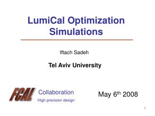
Preliminary LumiCAL FEE Specification. Presented by Alexander Solin NC PHEP solin@hep.by. FCAL collaboration meeting , February 12-13, 2006, Krakow ( INP PAS) , Poland. Contents. Preliminary LumiCAL FEE Specification

E N D
Preliminary LumiCAL FEE Specification Presented by Alexander Solin NC PHEP solin@hep.by FCAL collaboration meeting, February 12-13, 2006, Krakow (INP PAS), Poland
Contents • Preliminary LumiCAL FEE Specification • ASICs for FCAL detectors prototypes (main parameters measurement setup, bench and beam tests) February 12-13, 2006, Krakow A.Solin
Preliminary LumiCAL FEE Specification February 12-13, 2006, Krakow A.Solin
Estimation of the padSi-sensor capacitancies February 12-13, 2006, Krakow A.Solin
Estimation of the stripSi-sensor capacitancies February 12-13, 2006, Krakow A.Solin
Estimation of the maximum Si-sensor charge collection (1-1000)MIP channel signal range from B.Pawlik’s talk February 12-13, 2006, Krakow A.Solin
LumiCal Si-sensorparameters February 12-13, 2006, Krakow A.Solin
LumiCAL ASIC requirements February 12-13, 2006, Krakow A.Solin
ASIC technologies Next four pictures can help to estimate noises of frond end electronics. Calculations are done for Bi-JFET technology (see picture). Same calculations can be done for other technologies. Preamplifier noises will be similar to the presented calculations. February 12-13, 2006, Krakow A.Solin
Capacitance of Si-sensor vs its area 572pF 28pF February 12-13, 2006, Krakow A.Solin
ENC vs preamplifier power consumption 8000e February 12-13, 2006, Krakow A.Solin
ENC vs shaping time 8000e February 12-13, 2006, Krakow A.Solin
ENC vs Si-sensor Capacitance 572pF February 12-13, 2006, Krakow A.Solin
ASICs for FCAL detectors prototypes(main parameters measurement setup, bench and beam tests) February 12-13, 2006, Krakow A.Solin
Tetrode-BT, Tetrode-JFET ASICs 1996 year, CMS ECAL Two designs CSP were made in Minsk NC PHEP withslightly different circuits for amplifying of signals from Hamamtsu R2149 vacuum phototetrode: “TETRODE-BT” with bipolar input transistor; “TETRODE-JFET” with p-JFET input transistor. February 12-13, 2006, Krakow A.Solin
Design requirements to Tetrode CSPs Hamamtsu R2149 parameters: CSP requirements: February 12-13, 2006, Krakow A.Solin
CSP based on Tetrode JFETENC=320e+18e/pF, Tp=800ns February 12-13, 2006, Krakow A.Solin
AS01PDA, AS01T ASICs 2002 year, TESLA THCAL NextAS01PDA ASIC were designed and manufactured in Minsk NC PHEP for amplifying of signals from photodetectors. The AS01PDA ASIC is a development of the “Tetrode BT” design line. It additionally contains a shaper and shaper gain control stage. February 12-13, 2006, Krakow A.Solin
AS01PDAmain parameters February 12-13, 2006, Krakow A.Solin
AS01PDA block diagram February 12-13, 2006, Krakow A.Solin
AS01PDA tests • October, 2002 • Output signals were digitalized with theTDS3032 scope. February 12-13, 2006, Krakow A.Solin
AS01PDA noise curves • February, 2006 • Noise is measured with the Infiniium 54830B scope. February 12-13, 2006, Krakow A.Solin
ASIC for large capacitance detectors AS01T is optimazed for using with large capacitance detectors. • It has the same structure as AS01PDA. • The package is the same too. • Both chips (AS01T and AS01PDA) are placed on the same wafer and are manufactured in one process. February 12-13, 2006, Krakow A.Solin
Conclusion The next steps of development of FEE for FCAL • Making of readout electronics for immediate beam tests (Tetrode, AS01 ASICs) • Qualification of LumiCAL ASIC specification and design of new prototype of 22 channel preamplifier-shaper ASIC for amplifying of Si-detector signals. • Creation of multichannel readout electronics for larger FCAL prototypes. February 12-13, 2006, Krakow A.Solin